Draw The Shear Diagram For 0 X 14 Ft Of The Compound Beam
M 450x 4 0 v 1050 150x cf y 0 150x 4 v 450 0 m lb ft v lb 200 200 450 475 450 x x ans. D y 91875 1225 0 d y 30625 lb m d 0.
Solution
1225162 c y182 0 c y 91875 lb c f y 0.

Draw the shear diagram for 0 x 14 ft of the compound beam. Draw the shear and moment diagrams for the beam shown in the figure. B m 0 v 52100 150x6 lb c f y 0. M kn 65 140 50 25 v m kn kn.
875 150x v 0 0 x12 ft c f y 0. Shear and moment diagrams draw the shear and moment diagrams for the following beam 12 ft. Draw the shear force and bending moment diagrams for this beam.
M 0 0 problem 45 15 the uniformly loaded beam abc has simple supports at a and. Draw the shear and moment diagrams for the beam and determine the shear and moment in the beam as functions of x where 4 ft x 10 ft. 14 ft of the compound beam.
The shaft is supported by a smooth thrust bearing at a and a smooth journal bearing at b. A m 75x2 1050x 3200 ans 200 150x 4 x 4 2 m 0. 100010 200 20 0 490 lb b y y m a a m 50x 490 v m v 490 v lb 980 x 510 m lbft 2401 200 fig a fig b 5 15.
Home study engineering mechanical engineering mechanical engineering questions and answers draw the shear diagram for 0. Draw the shear and moment diagrams for the beam. 200 lb ft b x 4 ft 4 ft 150 lbft 6 ft 200 lb ft a ans.
Ft 150114 x2a 14 x 2 m 0. A y 1225 2100 0 a y 875 lb. The support at a is a thrust bearing and at b it is a journal bearing.
B end of internal loads part 3 any questions. Draw the shear and bending moment diagrams for the beam. Shear and moment diagrams draw the shear and moment diagrams for the following beam 10 ft.
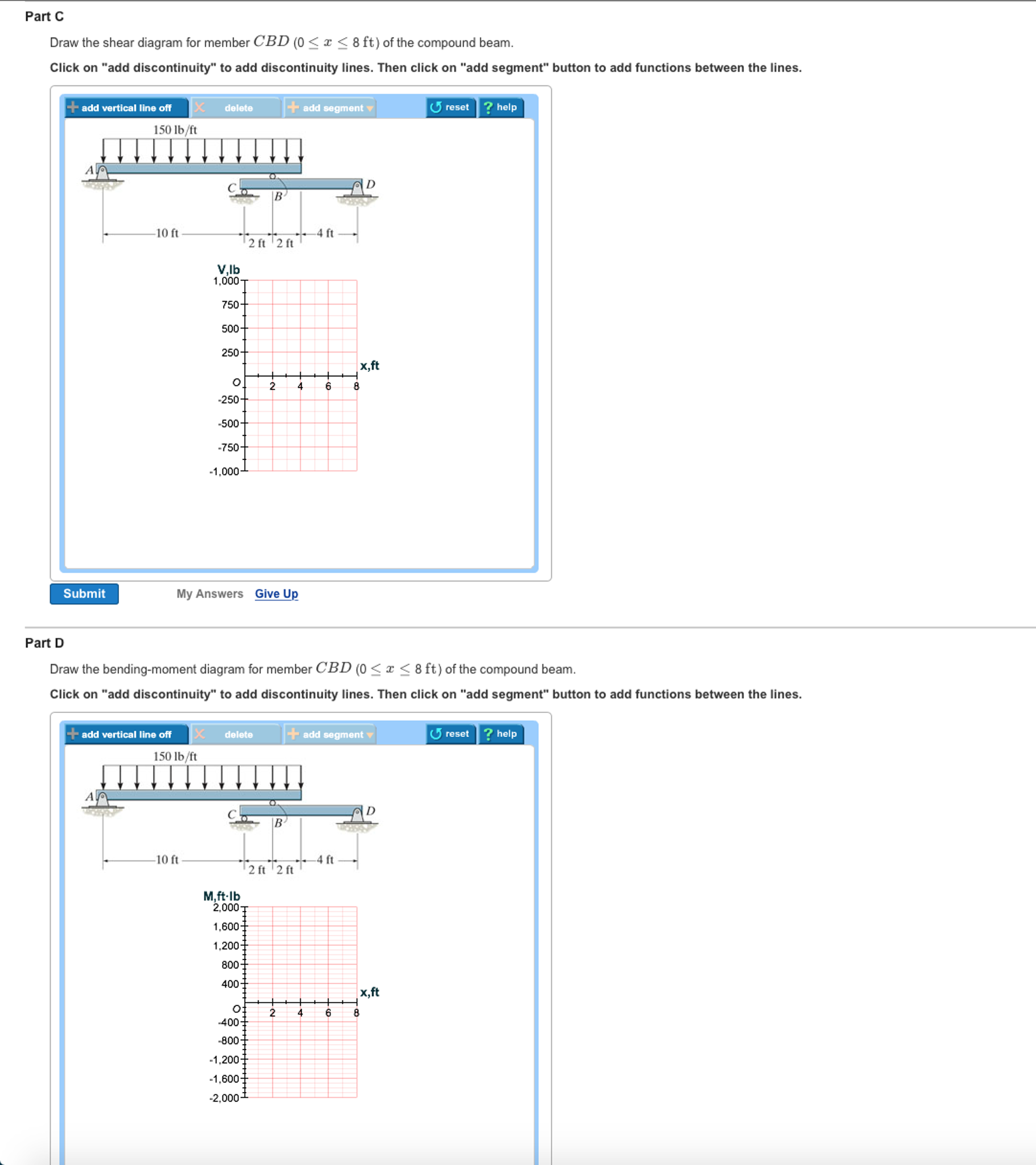
Solution 45 14 cantilever beam 276 chapter 4 shear forces and bending moments a b 2 m 2 m 25 kn 20 knm a b 2 m 2 m 25 kn 20 knm r a 65 m a 14 kn. 9 m 20 knm. Part d draw the bending moment diagram for member cbd 0 x 8 ft of the compound beam.
Part c draw the shear diagram for member cbd 0 x 8 ft of the compound beam. V 150114 x2 0 12 ftx 14 ft m 5875x 750x26 lb ft m 150xa x 2 m 0. 60 k 8 ft.
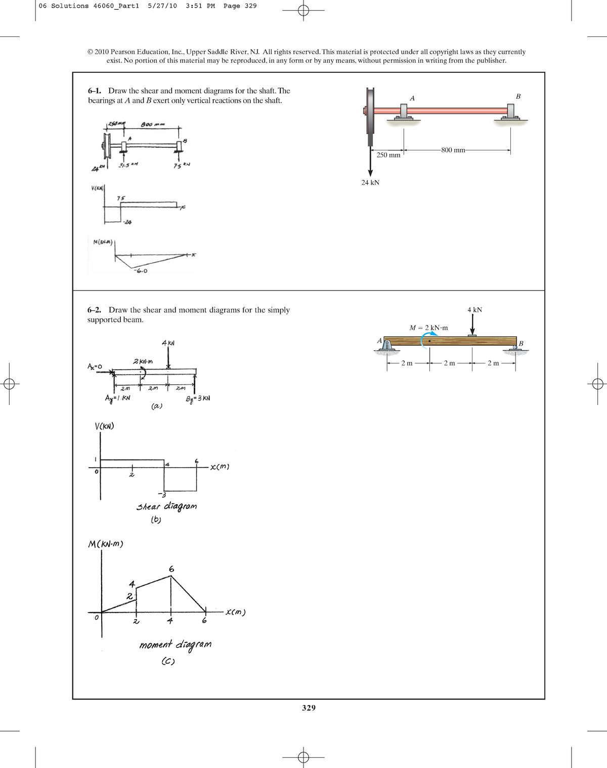
Draw the shear and moment diagrams for the shaft. B 875x 0 v 5875 150x6 lb c f y 0. 14 ft of the compound beam.
14 ft of the compound beam. The problem statement all variables and givenknown data draw the shear diagram for the compound supported beam. 14 ft of the compound beam.
9 6khdu rufh dqg hqglqj 0rphqw ldjudpv. Draw the shear diagram for 0. Draw the shear and moment diagrams for the beam.
Part a draw the shear diagram for 0 x part b draw the bending moment diagram for 0 x 14 ft of the compound beam.
 Shear Diagram V Wiring Diagram
Mechanics Of Materials Chapter 4 Shear And Moment In Beams
329 6 1 Draw The Shear And Moment Diagrams For The Shaft The
250 7500 0 2 V X N
 Determine The Normal Force Shear Force And Moment At Point C
Internal Loadings The Internal Torque Developed In Segments Ab And
Solution
Solution
329 6 1 Draw The Shear And Moment Diagrams For The Shaft The
Internal Loadings The Internal Torque Developed In Segments Ab And
Mechanics Of Materials Chapter 4 Shear And Moment In Beams
329 6 1 Draw The Shear And Moment Diagrams For The Shaft The
250 7500 0 2 V X N
329 6 1 Draw The Shear And Moment Diagrams For The Shaft The
250 7500 0 2 V X N
 Solved Draw The Shear Diagram For 0 X 14 Ft Of The Co
Mechanics Of Materials Chapter 4 Shear And Moment In Beams
250 7500 0 2 V X N
Internal Loadings The Internal Torque Developed In Segments Ab And
 Chapter 06 Solution Manual Mechanics Of Materials Studocu
Solution
Solution
Pdf Shear Forces And Bending Moments Shahin Alam Academia Edu
Chapter 06 Solution Manual Mechanics Of Materials Studocu
Internal Loadings The Internal Torque Developed In Segments Ab And
329 6 1 Draw The Shear And Moment Diagrams For The Shaft The
 Determine The Equation Of The Slope And Elastic Curve Ei Is Constant
Internal Loadings The Internal Torque Developed In Segments Ab And
0 Response to "Draw The Shear Diagram For 0 X 14 Ft Of The Compound Beam"
Post a Comment