Draw The Shear Diagram For The Compound Beam Which Is Pin Connected At B
Problem 67 part a draw the shear diagram for the compound beam which is pin connected at b click on add vertical line to add discontinuity lines. The beam consists of two segments pin connected at b.
 Chapter 06 Studocu
The compound beam is fixed at a.

Draw the shear diagram for the compound beam which is pin connected at b. 0 cv 400 n tef. The beam rests on a foundation that produces a uniformly distributed load over the entire length. Draw the shear and moment diagrams for the beam.
The compound beam is fixed at a pin connected at b and supported by a roller at c. Reset help add vertical line off delete add segment v 6 kip 8 kip 4 ft 6 ft 4 ft 4 ft 15 6 submit my answers give u. It is often necessary to draw shear and moment.
The compound beam is fixed at a pin connected at b and supported by a roller at c. But with the given loading it is balanced and will remain as shown if not disturbed 11 25 draw the shear and moment diagrams for the beam and determine the shear and moment in the beam as functions of x where 12 m x 3 m. Ti 2 4002l.
Draw the shear and moment diagrams for the beam. Draw the shear and moment diagrams for the beam. 700 lb 8 ft 4 ft 6 ft 9400 lbft 150 lbft v lb xft xft m lbft 1017 0 317 583 8 141 18 8 9400 1267 162 800 334 9 15.
400 n31 support reactions. Drawing shear force and bending moment diagram for a compound beam. Shear and moment diagrams for frames a frame is a structure composed of several members that are either fixed or pinconnected at their ends.
Posted one year ago the compound beam is fixed at a pin connected at b and supported by a roller at c. Draw the shear and moment diagrams for the beam. Then click on add segment button to add functions between the lines.
Skip navigation sign in. Drawing shear force and bending moment diagram for a compound beam. Draw the shear force and bending moment diagrams for this beam.
Draw the shear and moment diagrams for the beam. Pin connected at 6001 b. Problem 45 12 the beam ab shown in the figure supports a uniform load of intensity 3000 nm acting over half the length of the beam.
The beam consists of two segments pin connected at b. And supported by a roller at c. Referring to the freebody diagram of segment bc shown in fig.
Draw the shear and moment diagrams for the beam. The compound beam is fixed at a pin connected at b and supported by a roller at c. 8 ft 4 ft 6 ft 700 lb 150 lbft 800 lb и ft a b c 7 solutions 44918 12709 1039 am page 626 83.
Untitled
![]() Solved Draw The Shear Force And Bending Moment Diagram Of The
Solved Draw The Shear Force And Bending Moment Diagram Of The
329 6 1 Draw The Shear And Moment Diagrams For The Shaft The
329 6 1 Draw The Shear And Moment Diagrams For The Shaft The
Solved The Compound Beam Is Fixed At A Pin Connected At
 Shear And Moment Diagram For Beam With Hinge Mechanics Of
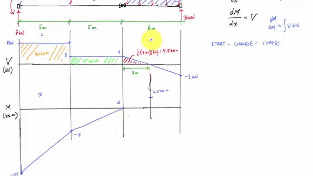
 English Compound Beam Shear And Moment Diagram Youtube
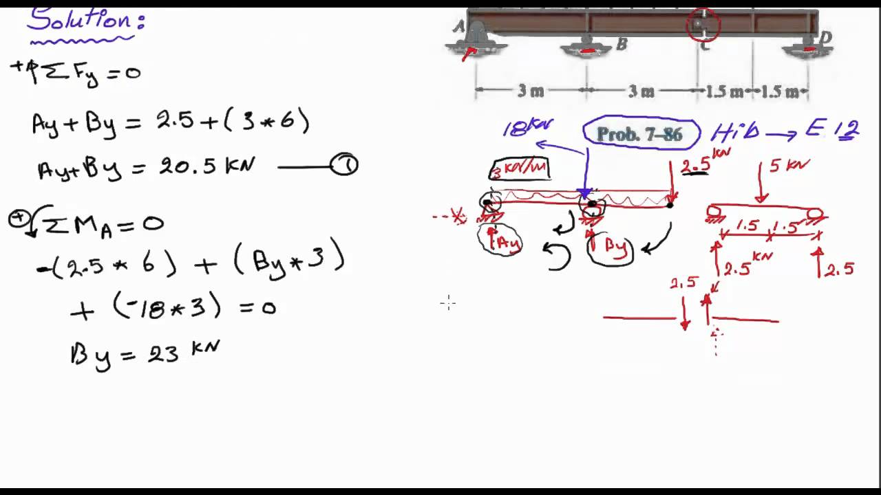
 Hibbeler Statics Solution Chapter 7 1
Solution
 Solved Draw The Shear And Moment Diagrams For The Compound Beam
Draw Shear And Moment Diagram For Beam Facebook
 Calculating Reactions For Beam With Hinge Statics Mechanics
329 6 1 Draw The Shear And Moment Diagrams For The Shaft The
 Hibbeler Statics Solution Chapter 7 1
Mechanics Of Materials Chapter 4 Shear And Moment In Beams
Solution Manual Mechanics Of Materials R C Hibbeler Chapter
 Determine The Normal Shear Force And Bending Moment At C And D
 Hibbeler Statics Solution Chapter 7 1
Draw Shear And Moment Diagram For Beam Facebook
 Solved Draw The Shear And Moment Diagrams For The Compoun
 Hibbeler Statics Solution Chapter 7 1
Solutions Set 01 Assignment Answers Civ E270 Mechanics Of
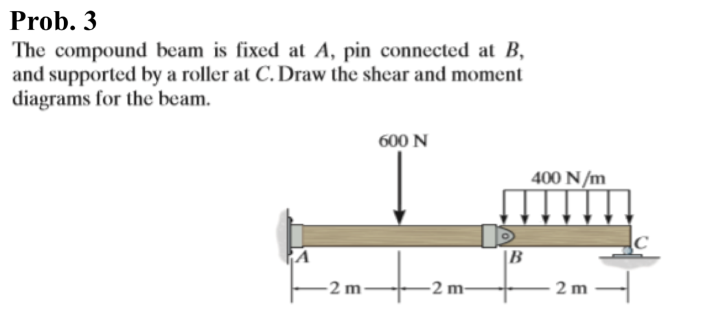 Solved Prob 3 The Compound Beam Is Fixed At A Pin Conne
 Chapter6 140504131032 Phpapp02
Chapter6 140504131032 Phpapp02
Mechanics Of Materials Chapter 4 Shear And Moment In Beams


0 Response to "Draw The Shear Diagram For The Compound Beam Which Is Pin Connected At B"
Post a Comment