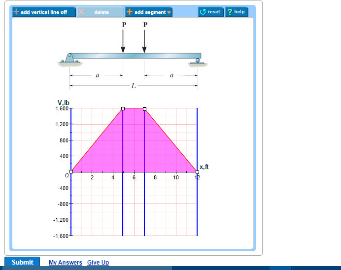
Draw The Shear Diagram For The Beam Set P 800 Lb A 5 Ft L 12 Ft
Draw the shear and moment diagrams for the beam a in terms of the parameters shown. Draw the moment diagram for the beam.
 Ch 7 Solution Manual Engineering Mechanics Statics Dynamics
Set p 800 lb a 5 ft l 12 ft.
Draw the shear diagram for the beam set p 800 lb a 5 ft l 12 ft. 800 lb of shear force is uniformly distributed along segment ab. Then click on add segment button to add functions between the lines. Plz help in this question.
The beam consists of two segments pin connected at b. L 12 ft. Click on add discontinuity to add discontinuity lines.
Click on add discontinuity to add discontinuity lines. A a l p p prob. The slope of the shear diagram over the interval 2l x 3l is zero since wx 0.
I calculating reactions at 215 ii. Vbc 2400 800x is linear. Click on add discontinuity to add discontinuity lines.
7 72 s hear and m oment e quations and d iagrams 353 756. This is a detailed example of shear and moment diagrams i recommend skipping around to the sections shown below if you already have a feel for the subject. Set p 800 lb a 5 ft l 12 ft.
When vbc 0 2400 800x 0 thus x 3 ft or vbc 0 at 1 ft from b. B set p 800 lb a 5 ft l 12 ft. 8 ft 4 ft 6 ft 700 lb 150 lbft 800 lb и ft a b c 7 solutions 44918 12709 1039 am page 626 83.
Draw the shear diagram for the beam. The resulting shear diagram matches the shear at the right end determined from the equilibrium equations. Establish the m and x axes and plot the value of the moment at each end.
Draw the shear and moment diagrams for the beam. At x 6 ft vbc 2400 lb. Draw the shear diagram for the beam.
Then click on add segment button to add functions between the lines. At x 2 ft vbc 800 lb. 747 problems subscribe to view the full document.
To draw the shear diagram. Set p 800 lb a 5 ft.
 Solved Plz Help In This Question Part A Draw The Shear D
Solved Draw The Moment Diagram For The Beam Set P 800
Solution
Solution
 Hibbeler Statics 12 Ed Cap 7 2
Solution
 Hibbeler Statics Solution Chapter 7 1
Chapter 06 Solution Manual Mechanics Of Materials Studocu
Ch7
 Solved Draw The Shear And Bending Moment Diagrams For The
 Hibbeler Statics Solution Chapter 7 1
Hibbeler Chapter 6 Part 1 463 486 Qxd
 Hibbeler Statics 12 Ed Cap 7 2
Hibbeler Statics 12 Ed Cap 7 2
 Draw The Shear And Bending Moment Diagrams For The Beam Set P 800
 Determine The Normal Shear Force And Bending Moment At C And D
Solution
 Draw The Shear And Bending Moment Diagrams For The Beam A In Terms
Ch 7 Solution Manual Engineering Mechanics Statics Dynamics
 Engineering Mechanics Statics Pages 351 400 Text Version Fliphtml5
329 6 1 Draw The Shear And Moment Diagrams For The Shaft The
Ch 7 Solution Manual Engineering Mechanics Statics Dynamics
Chapter 06 Solution Manual Mechanics Of Materials Studocu
Chapter 06 Solution Manual Mechanics Of Materials Studocu
 Draw The Shear And Bending Moment Diagrams For The Beam Set P 800
 Hibbeler Statics Solution Chapter 7 1
Solution Manual Strength Of Materials R C Hibbeler H1 7
 Draw The Shear And Bending Moment Diagrams For The Beam A In Terms
 Hibbeler Statics Solution Chapter 7 1
329 6 1 Draw The Shear And Moment Diagrams For The Shaft The
7 Solutions 44918
Solution


0 Response to "Draw The Shear Diagram For The Beam Set P 800 Lb A 5 Ft L 12 Ft"
Post a Comment