Which Of The Following Is The Correct Free Body Diagram Of A Truss Member In Equilibrium
Hints 3 hint 1. Check all that apply.
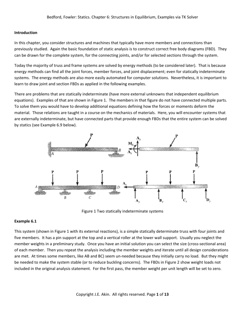 Bedford Fowler Statics Chapter 6 Structures In Equilibrium
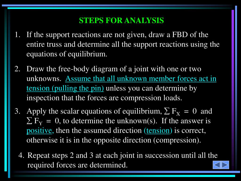
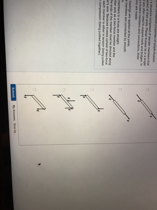
Tensile forces should originate at the joint previous 1 of2 net the vectors starting or ending at the appropriate black dots.

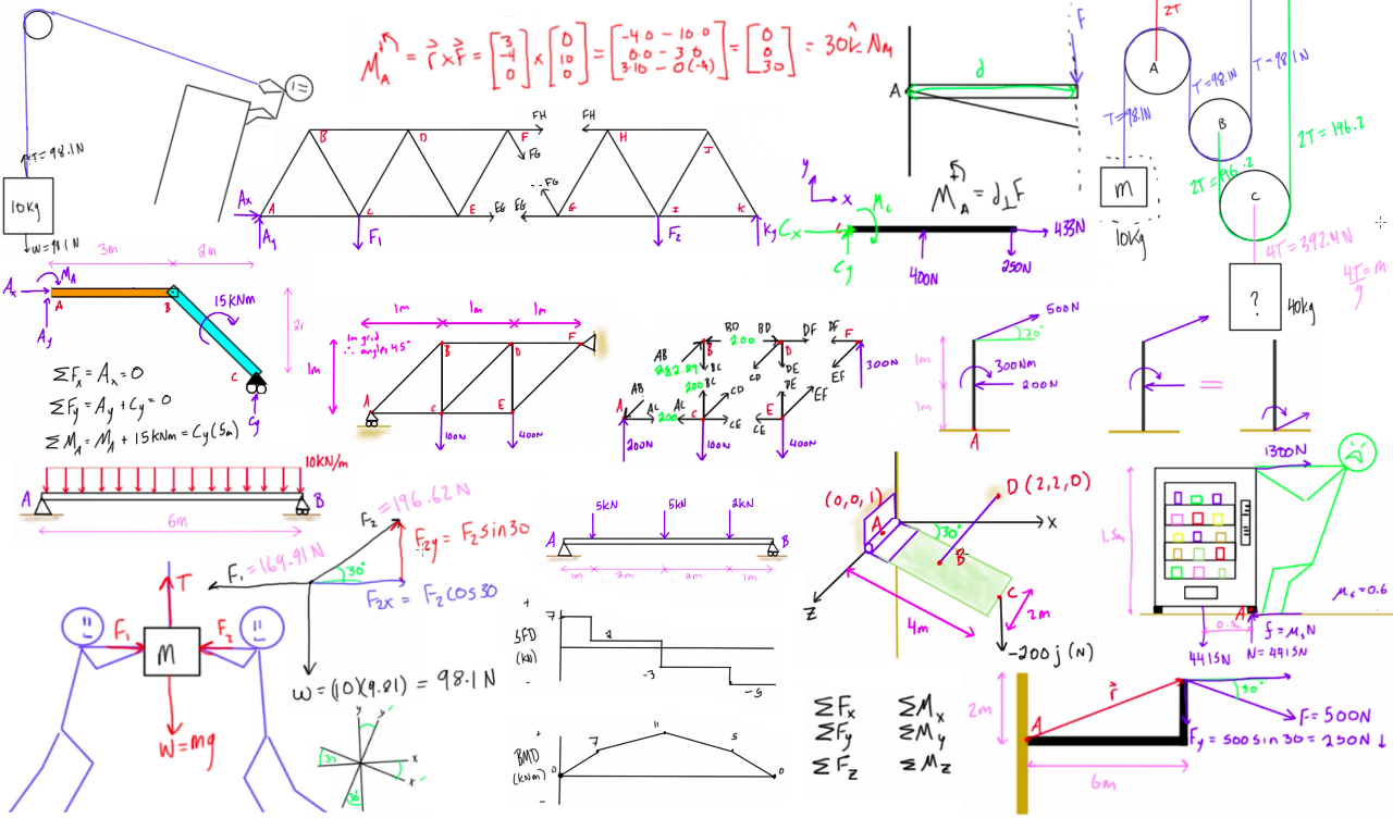
Which of the following is the correct free body diagram of a truss member in equilibrium. The upper left member is in compression and the lower right member is in tension. The free body diagram of the two truss members by adding the forces that act on them. Compressive forces should terminate at the joint.
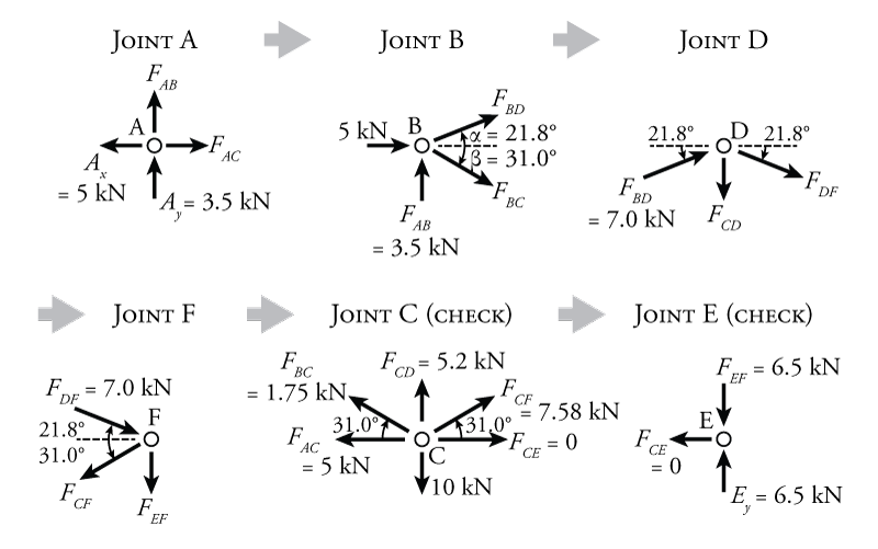
Tensile forces should originate at the joint. Desired member forces are determined by considering equilibrium of one of the two fbd of the truss. Part e which of the following is the correct free body diagram of a truss member in equilibrium.
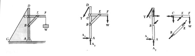
Compressive forces should terminate at the joint. Which of the following is the correct free body diagram of a truss member in equilibrium. Method of sections involves cutting the truss into two portions free body diagrams fbd by passing an imaginary section through the members whose forces are desired.
The mathematics of rafter and collar ties analysis some definitions mathematically rafter and collar ties are handled the same way however each type of tie has a different purpose question paper sewage treatment scribd is the world s largest social reading and publishing site. The conditions for rotational equilibrium are. Specific truss members directly.
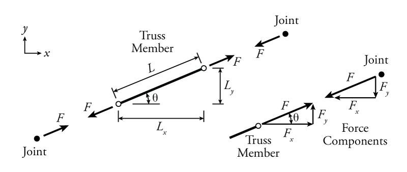
How to approach the problem for a truss member to be in equilibrium the sum of the forces and the sum of the moments about any point o on the member must be zero. The upper left member is in compression and the lower right member is in tension. View the full answer.
Complete the freebody diagram of the two truss members by adding the forces that act on them. For the first figure the moment applied on the bar is capable of producin.
 Of Equilibrium Pass A Section Through The Truss And The Member Whose
 Analysis Of Structures
Structural Analysis
 The Free Body Diagram Of Truss Unit Cells Under A In Plane
 Ppt Simple Trusses The Method Of Joints Zero Force Members
 Evolution Of Trusses
Untitled
 Statics Engineer4free The 1 Source For Free Engineering Tutorials
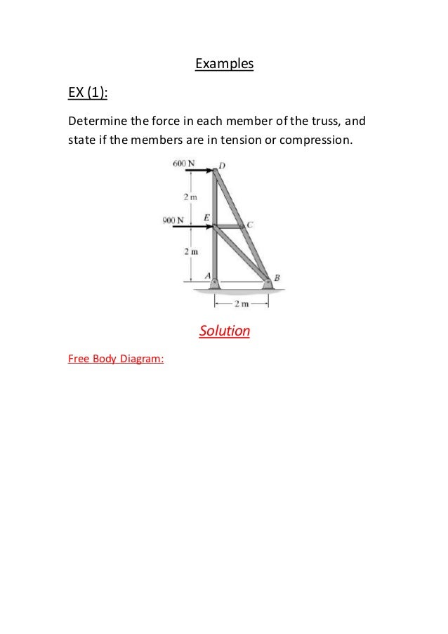 Truss Examples
18 Free Body Diagrams Statics Physics Forums
 Chapter 6 Structure Analysis Flashcards Quizlet
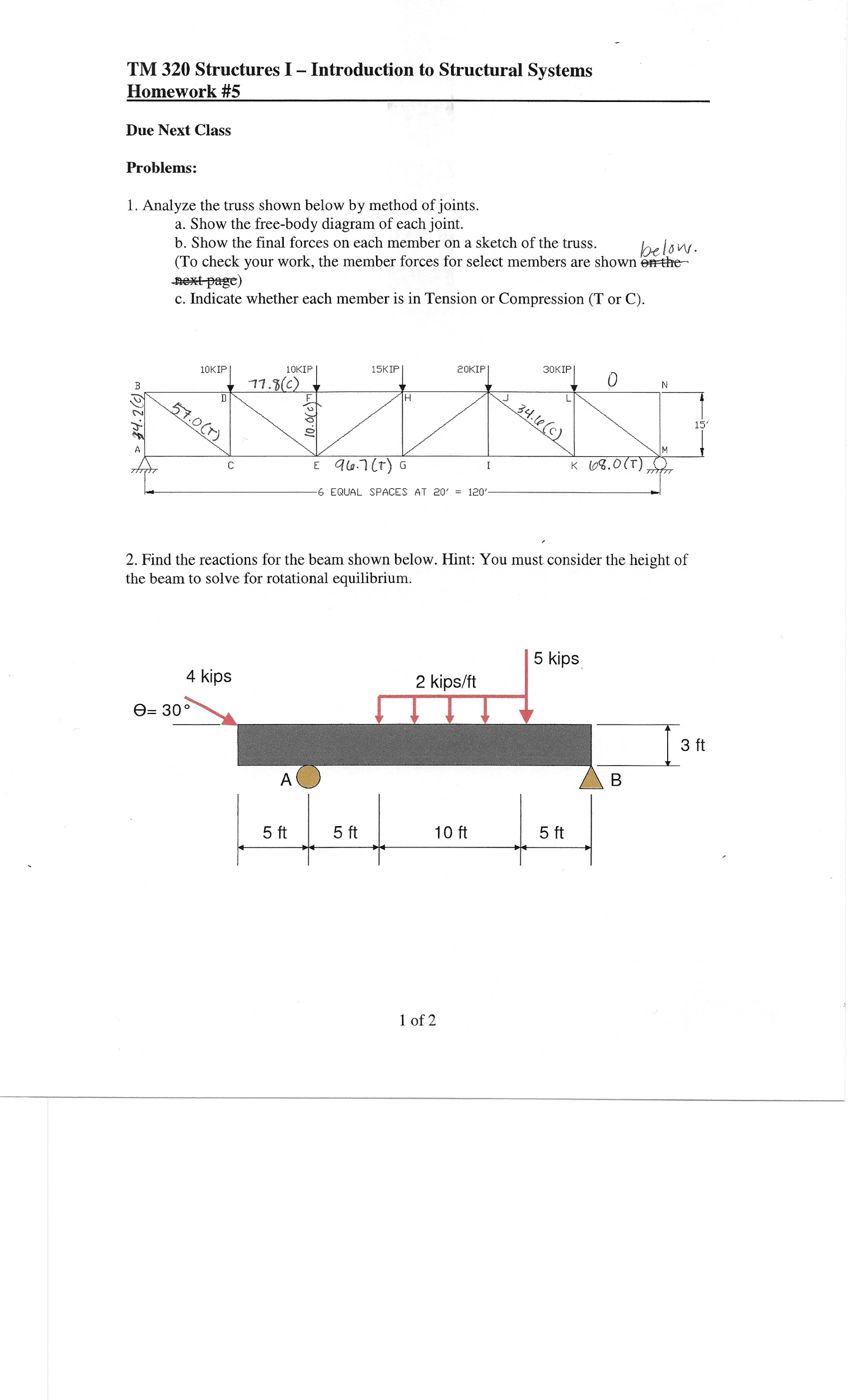 Solved Analyze The Truss Shown Below By Method Of Joints
Solution
 3 Methods For Truss Analysis Engineersdaily Free Engineering


18 Free Body Diagrams Statics Physics Forums
 Using The Method Of Joints Determine The Force In The Member Ab And
4 Solving Statics Problems
Show Fbds For The Entire Truss And The Cut Section Used In Your
Form Diagram Force Diagram Free Body Diagram
Untitled
Statics No Motion
0 Response to "Which Of The Following Is The Correct Free Body Diagram Of A Truss Member In Equilibrium"
Post a Comment