Step Dimming Ballast Wiring Diagram
Page 666 ballast control module eight channels of 0 10vdc dimming with integrated 20a relays for four wire dimming ballasts. Available with 120v 277v and 347v circuit breakers.

You could be a service technician that wants to try to find recommendations or resolve existing troubles.

Step dimming ballast wiring diagram. Trying to find info concerning lutron dimming ballast wiring diagram. Dimmable ballast wiring diagram. Use the drop down menu here to search for any product wiring diagram made by lutron.
Register for mylutron forgot my password. Dimmer module six universal load digital dimmers suitable for 120v or 277v incandescent fluorescent low voltage neon cold cathode and non dim loads. Step dimming ballasts are relatively inexpensive and often used with occupancyvacancy sensors or automatic timers to optimize energy usage.
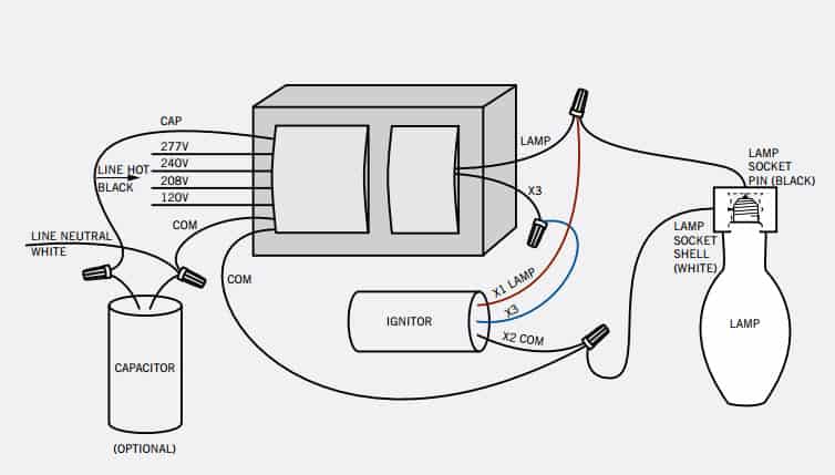
Incoming power from branch must be on same phase. Dimming cfls and leds. 13 sockets and lampholders 16 lamp wiring diagrams 19 ballast control types 20 ecosystem ballasts 22 emergency backup ballast 24 ballast troubleshooting 25 installation best practices 26 appendix a.
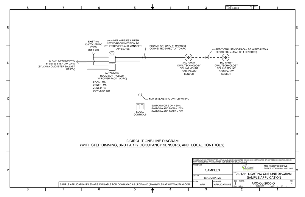
Lead placement on wiring diagram is optimized for clarity and not intended to reflect actual lead exit locations on sd case. You are right below. Wall switches s1 s2 should be located next to each other to allow for full on low on off control.
These ballasts use two line voltage switches for selecting operation at full intensity or at half power. Series ballasts can only be wired in series according to the diagram on the ballast. Fluorescent dimming systems technical guide 02 lutron fluorescent dimming ballasts 04 how it works 05 lamp.
Ge ultramax ballasts provide a wide variety t8 step dimming ballast. Parallel ballasts can only be wired in parallel according to the diagram on the ballast. 0 10v or 4 wire dimming ballasts provide continuous light output typically 5 to 100 based on the input voltage of the 0 10v line.
0 10v dimming wiring diagram 0 10v dimmer switch leviton ip710 lfz or equal for other types of dimming control systems consult controls manufacturer for wiring instructions switched hot black switched hot red typical low voltage dimming wires purple gray typical electrical panel hot black typical 120v or 277v 60 hz neutral white. Quick easy troubleshooting. Enables or disables daylight sensor operation and controls the set pointwhen enabled the sensor turns lights on in response to occupancy when light levels are below the daylight sensor set point.
Search the lutron archive of wiring diagrams. To find a diagram for a specific product or system please use. Changing the wiring on a fluorescent light fixture from series to parallel involves changing the ballast from a series to a compatible parallel ballast.
Page 3 switches 10 11 12 daylight sensor set point levels. Application note 28 appendix b. Step dimming control facilitates energy code compliance without installation of low voltage control wiring.
Or you are a student or perhaps even you who just want to know concerning lutron dimming ballast wiring diagram. Do not use with multiple phases. How to install a dimmer.
The levelpro family of ballasts is designed for maximum energy savings and high efficiency and they are cee compliant.

 Dimming Ballast Wiring Diagram Wiring Diagram Schematics
 Dimming Keystone Technologies
 Step Dimming Wiring Diagram Wiring Diagrams
 Step Dimming Ballast Wiring Diagram Wiring Diagram
 Step Dimming Ballast Wiring Diagram Wiring Diagram
H Moss Occupancy Sensors H Moss

 73229 Ge Lfl Ultramax Step Dimming Electronic Dimming Ballast
 71497 Ge Lfl Ultramax Step Dimming Electronic Dimming Ballast

 Step Dimming Ballast Wiring Diagram Wiring Library
 58 Good Thought Image Of T8 Dimming Ballast Wiring Diagram Wiring
 Step Dimming Ballast Wiring Diagram Wiring Diagram

 0 10v Dimming Ballast Wiring Diagram Wiring Diagram
 Advance Dimming Ballast Wiring Diagram Wiring Diagram
 Dimming Ballast Wiring Diagram 3 Wire Wiring Diagram
 Dimming Ballast Wiring Diagram Dimming Ballast Wiring Diagram


0 Response to "Step Dimming Ballast Wiring Diagram"
Post a Comment