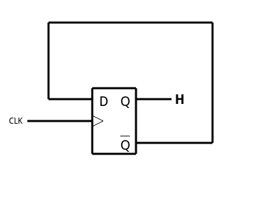
Toggle Flip Flop Timing Diagram
When t1 and cp1 the flip flop complements its output regardless of the present state of the flip flop. Joe haas 17374 views.
 Flip Flop Truth Table Various Types Basics For Beginners
Q goes high and q goes low.

Toggle flip flop timing diagram. Overview last lecture introduction to sequential logic and systems the basic concepts a simple example today latches flip flops edge triggered d master slave timing diagrams t flip flops and sr latches cse370 lecture 14 2 the d latch output depends on clock clock high. Although this circuit is an improvement on the clocked sr flip flop it still suffers from timing problems called race if the output q changes state. This results in the jk flip flop acting more like a t type toggle flip flop when both terminals are high.
Jk flip flop timing diagrams duration. It is the basic storage element in sequential logicflip flops and latches are fundamental building blocks of. Similarly a t flip flop can be constructed by modifying d flip flop.
The circuit diagram of a t flip flop constructed from sr latch is shown below. A flip flop is a bistable multivibratorthe circuit can be made to change state by signals applied to one or more control inputs and will have one or two outputs. These flip flops are called t flip flops because of their ability to complement its state ie toggle.
To explain the operation of the common latches and flip flops sr or setreset latch which may also be called a sr flip flop d or data flip flip t or toggle flip flop jk flip flop to describe clocking and the differences between positive edge. So they are called as toggle flip flop. We will assume an initial condition t 0 of q being low and q being high.
At t 1 the toggle changes from a low to a high and the device changes state. The timing diagram in figure 3 15 view b shows the toggle input and the resulting outputs. Jk flip flop jack kilby t flip flop toggle out of the above types only jk and d flip flops are available in the integrated ic form and also used widely in most of the applications.
When a toggle flip flop is used as one stage of a counter its q output changes to the opposite state it toggles high or low on each clock pulse. This flip flop has only one input along with clock pulse. So these flip flops are also called toggle flip flops.
Here in this article we will discuss about t flip flop. Most edge triggered flip flops can be used as toggle flip flops including the d type which can be converted to a toggle flip flop with a simple modification. Toggle t flip flop.
In d flip flop the output qprev is xored with the t input and given at the d input. Input passes to output. Jk flip flop c j k q hold.
The name t flip flop is termed from the nature of toggling operation. In electronics a flip flop or latch is a circuit that has two stable states and can be used to store state information. A description of the jk and t flip flops along with some example timing diagrams showing how they work.
 Learn Flip Flops With More Simulation Hackaday
 Rangkaian Sequensial Rs Flip Flop Jk Flip Flop T Flip Flop
 How To Draw Timing Diagrams For Flip Flops
 Flip Flops An Overview Sciencedirect Topics
 T Flip Flopi Sinhroni In Prozen Na Fronto Raziskal Slavko Murko
 Sequential Circuits Flip Flops Part 2
 Solved Suppose You Have A Master Positive Edge Triggered
 Digital Circuits And Systems Circuits I Sistemes Digitals Csd
 Ekt 121 4 Digital Electronics I Ppt Download
 Flip Flops And Latches Northwestern Mechatronics Wiki
 Asynchronous Counter T Flip Flop Timing Diagram Online Wiring Diagram
 Digital Circuits Conversion Of Flip Flops
 T Flip Flop Electronics Engineering Study Center
 T Flip Flop Circuit Diagram Inspirational T Flip Flop Schematic
 Navy Electricity And Electronics Training Series Neets Module 13
 Solved 2 More Flip Flops A Draw The Truth Table And Co
 Chantha Thoeun Flip Flop Circuits Types Of Flip Flops Sr Flip Flop
 Flip Flops Reference Digilentinc


0 Response to "Toggle Flip Flop Timing Diagram"
Post a Comment