Block Diagram From Transfer Function
It is also having one summing point and one take off point. It can be used together with transfer functions.
Feedback and controls systems by distefano et al.
Block diagram from transfer function. Arrows indicate the direction of the flow of signals. Also it can be used together with transfer functions to represent the cause and effect relationships throughout the system. It is used to represent all types of systems.
Some systems may have dedicated summation or multiplication devices that automatically add or multiply the transfer functions of multiple systems together simplifying block diagrams. This is a very useful tool because it facilitates in obtaining the equations of a system including the effects of a. Transfer function to block diagram in state space analysis control system 44 by sahav singh yadav duration.
Transfer function is defined as the relationship between an input signal and an output signal to a device. A system can be defined as a mathematical relationship between the input output and the states of a system. The transfer function of a component is represented by a block.
Ecm2105 control engineering. Transfer functions in block diagrams one source of transfer functions is from balance equations that relate inputs and outputs. 4 blocks in parallel rule.
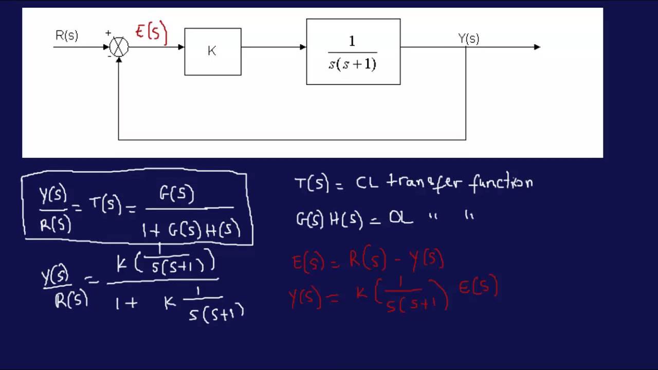
5 positive feedback loop rule. The above block diagram consists of two blocks having transfer functions gs and hs. How to find the transfer function of a siso system starting from the ordinary differential equation.
In control theory a system is represented a a rectangle with an input and output. 2 associative and commutative properties rule. Example problem on how to derive closed loop transfer function from block diagram.
Note that this table is from schaums outline. Gate crackers 25736 views. How to simulate a transfer function in an xcos block diagram.
6 negative feedback loop equivalent. Let us now discuss these elements one by one. Block diagrams can be systematically simplified.
Block diagram simplification rules equivalents. Transfer functions are compact representations of dynamic systems and the differential equations become algebraic expressions that can be manipulated or combined with other expressions. How to simulated a transfer function using scilab dedicated functions.
3 distributive property rule. A block diagram can be used simply to represent the composition and interconnection of a system. Block diagram of transfer functions in the laplace domain see fig.
It is defined as the ratio of the laplace transform of the output variable to the laplace transform of the input variable with all zero initial conditions.
 Solved Reduce The Block Diagram Shown In Figure P5 9 To A Single
Open Loop Transfer Function Block Diagram Awesome Avian S Blog
 Block Diagram 1 S Wiring Diagram
![]() Block Diagram From Transfer Function Wiring Diagram
Block Diagram From Transfer Function Wiring Diagram
Simulation Diagrams Of Laplace Transform
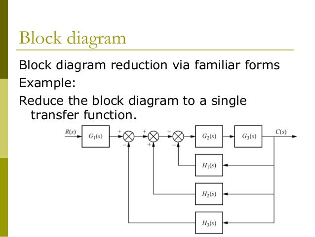
 Block Diagram Reduction Techniques Transfer Function
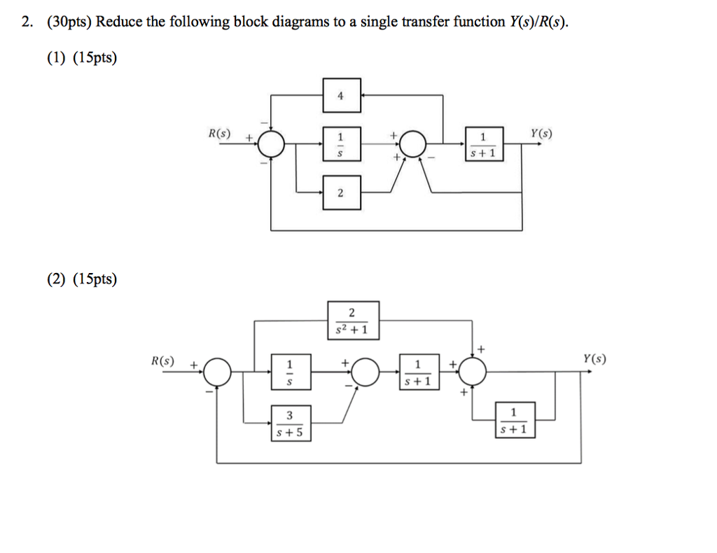
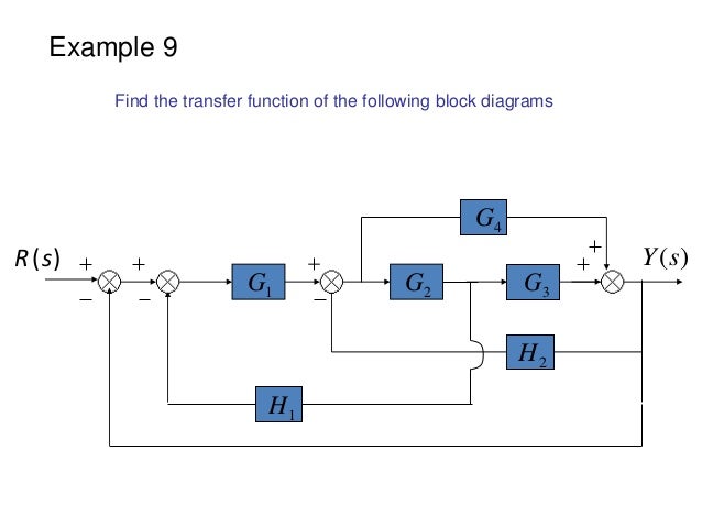 Block Diagram Examples
1 3 19 Find The Transfer Functions For The Block Diagrams In Fig
 Chapter 4 Transfer Function And Block Diagram Operations 4 1
 Block Diagram 1 S Wiring Diagram
 Function Of Block Diagram Wiring Diagrams Explo
 Simplify The Block Diagram Shown In The Figure Obtain The Transfer
 Wescott Design Services Using Block Diagrams
 Solved Reduce The Block Diagram Shown In Figure P5 1 To A Single
 Deriving Transfer Function From Block Diagram 1 Fe Eit Exam Review
 Block Diagram Of Electromechanical Systems Dc Motor
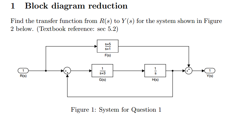
 Determine The Transfer Function Y S R S For The Chegg Com
 Block Diagram Solver Wiring Diagram Data Today
 Wescott Design Services Using Block Diagrams
![]() File Block Diagram For Sensitivity Transfer Function Svg Wikipedia
File Block Diagram For Sensitivity Transfer Function Svg Wikipedia
 Block Diagram To Transfer Function Simulink Wiring Diagram
 Block Diagram Transfer Function Of A Line Signal Processing Stack
 Solved Find The Transfer Function For The Block Diagram S
 Block Diagram To Transfer Function Simulink Wiring Diagram
![]() How To Find The Transfer Function Of A System X Engineer Org
How To Find The Transfer Function Of A System X Engineer Org


 Control System Getting Transfer Function From Block Diagram

Control Chap3
 Figure 2 From A Method Of Transfer Functions And Block Diagrams To
0 Response to "Block Diagram From Transfer Function"
Post a Comment