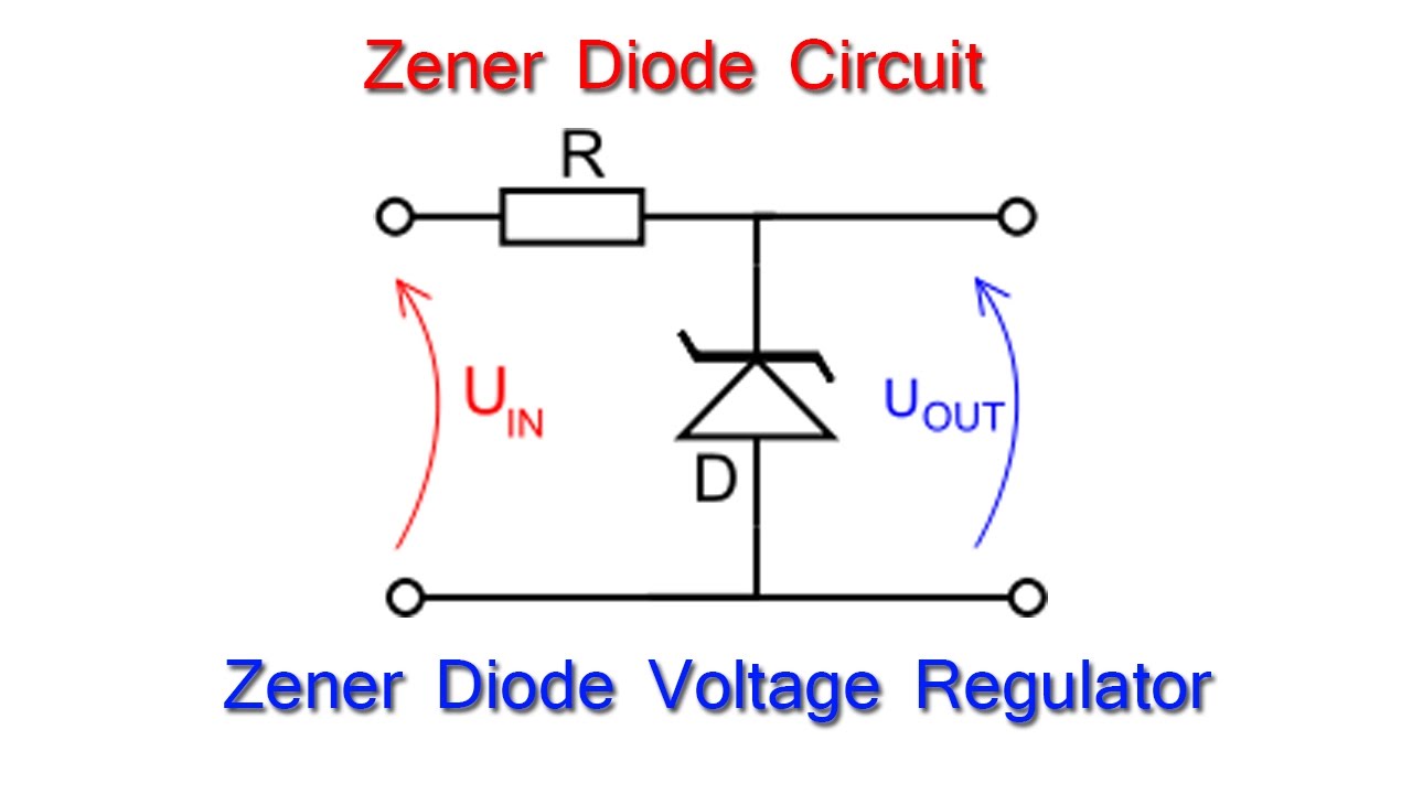
Zener Diode Circuit Diagram
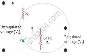
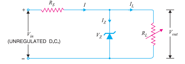
If the diode resistance r z is small compared to r s and r the zener diode model of figure 2 can be approximated as a battery of strength v z as shown in the simplified circuit of figure 4b. Figure 4 a a zener diode voltage regulator circuit diagram.
 What Is Zener Diode Operation Principle Types Uses Of Zener
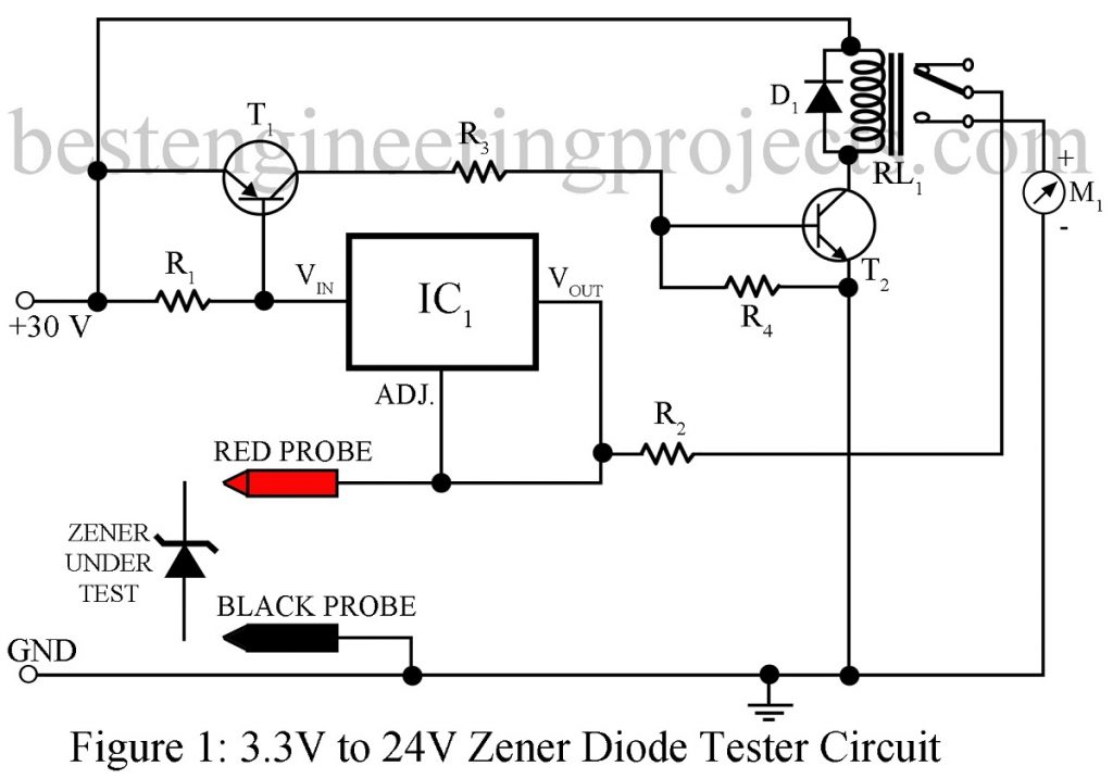
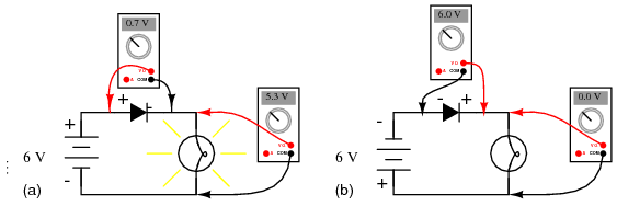
The circuit diagram of the diode tester here is made of simple transistors and resistors.

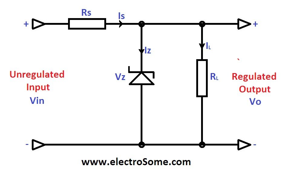
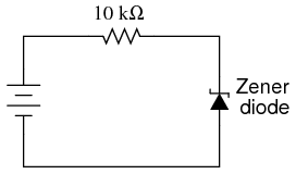
Zener diode circuit diagram. And b the simplest equivalent circuit. You can also test a zener diode by the use of this circuit too. The above shown simple shunt regulator is not mostly effective and not feasible for higher current applicationz.
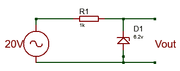
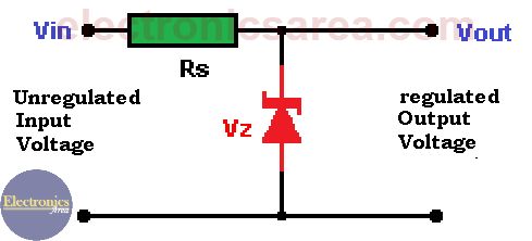
This zener diode circuit uses the zener diode in a slightly different way detecting the breakdown current through the diode once a certain voltage has been reached. The circuit diagram of the zener diode is shown in the figure below. Resistor value ohms v1 v2 zener current load current the above diagram is of a shunt regulators because the regulating element is parallel to the load element.
The simple circuit diagram is displayed below where the transistor is being used as emitter follower. A typical zener diode for general electronic circuits is the 500mw bzx55 series or the larger 13w bzx85 series were the zener voltage is given as for example c7v5 for a 75v diode giving a diode reference number of bzx55c7v5. Any kind of ic is not used in this circuit so it will be easy for the electronics beginners for understanding the working principal of diode tester in this circuit.
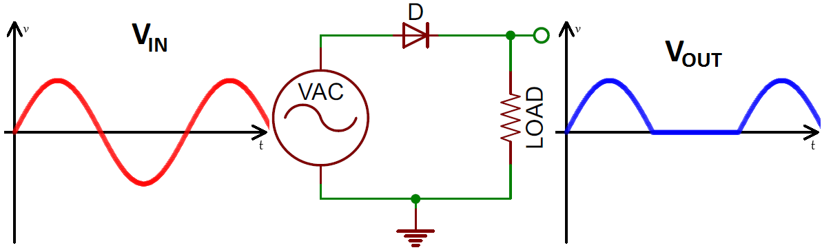
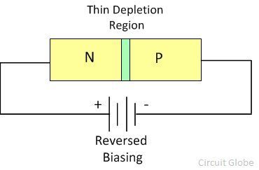
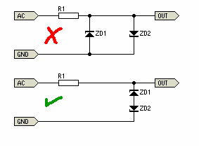
It allows the current to flow as like a normal pn junction diode when it is forward biased and block the reverse flow of current during the reverse bias up to the breakdown voltage. Zener diodes are widely used as voltage references and as shunt regulators to regulate the voltage across small circuits. Assuming that the potential at junction d1 d3 is positive with respect to that at d2 d4 and is greater than the zener voltage 06 v d3 will act as a zener and limit.
The zener diode is a type of diode which operates under reverse bias that breakdowns when the applied voltage reaches a particular reverse bias voltage or knee voltage. Another form of zener diode circuit is an overvoltage protection circuit. The supply described here uses two zener diodes and two rectifier diodes instead of the usual four rectifier diodes and one zener.
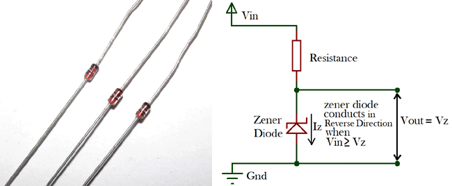
When connected in parallel with a variable voltage source so that it is reverse biased a zener diode conducts when the voltage reaches the diodes reverse breakdown voltage. Zener bridge rectifier circuit description. The zener diode is employed in reverse biasing.
The way out of it is to use a zener diode circuit with a seris pass transistor. The zener diode produces a stable reference voltage across the load which fulfills the criteria of regulator requirement. The reverse biasing means the n type material of the diode is connected to the positive terminal of the supply and the p type material is connected to the negative terminal of the supply.
Zener diode circuit for psu with series transistor.
 Diodes Learn Sparkfun Com
 Zener Diode Calculator Theory
 What Is Zener Diode Operation Principle Types Uses Of Zener
 Zener Diode Voltage Regulator
 Zener Diode As Voltage Regulator Tutorial
 Zener Diode Definition Vi Characteristics And Breakdown In Zener
 Super Steady Zener Diode Voltage Regulator Circuit
 Describe With The Help Of A Circuit Diagram The Working Of Zener
 Zener Diode Clipper Circuit Example 9 With Simulation Youtube

 Zener Diode Tester Circuit Engineering Projects
 Zener Diode As Voltage Regulator Tutorial
 Zener Diode Voltage Regulator Circuit Design Electronics Area
Circuit Diagram Zener Diode Characteristics Wiring Diagram Schematics
Zener Diode Voltage Reference Circuitlab


 Zener Diode Tester Circuit
 Zener Diode Basic Operation And Applications

 What Is Zener Diode Definition Working Characteristic Curve
 Zener Diode Symbol And Application As Voltage Regulator
 Zener Diode Voltage Regulator Circuit Diagram Electronic Circuits
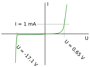
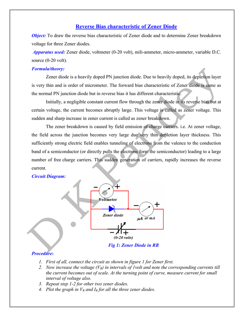 Reverse Bias Characteristic Of Zener Diode
 Diodes Learn Sparkfun Com
 Zener Diode Voltage Regulator Electronics Post
 Zener Diode Wikipedia
 Zener Diode Zener Diode As Voltage Regulator In Electric Circuit
 Circuit Diagram Diode Wiring Diagram Experts

 Voltage Regulator Discrete Semiconductor Circuits Electronics
 Zener Diode Working With Circuit Diagram And Applications
 Adjustable Zener Diode Eeweb Community
0 Response to "Zener Diode Circuit Diagram"
Post a Comment