4 Wire Transmitter Wiring Diagram
So the first thing that came out was a four wire transmitterin other words two. This is the 4 wire pressure transducer wiring diagram.
 Pressure Transducer Wiring Diagram Wiring Diagram Official
4 wire pressure transducer wiring diagram introduction to the two wire transmitter the 4 20ma whitepaper introduction to the two wire transmitter and the 4 20ma current loop.

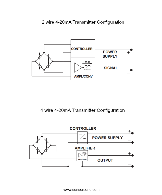
4 wire transmitter wiring diagram. The 4 ma zero end current is sufficient to drive the internal circuitry of the transmitter and the current from 4 to 20 ma represents the range of the measured process variable. 4 20 ma transmitter wiring. Please right click on the image and save the photo.
Here the transmitter is not really a current source in the sense that a 4 wire transmitter is. The design of the associated control panel dictates which option should be used. Four wire transmitters can be ac or dc powered.
Current source transmitter non isolated 3 wire current sink transmitter non isolated 3 wire fully isolated 4 wire two wire loop powered transmitters. Pressure transducer wiring diagram webtor img source. So ideas if you like to secure all these amazing pics about 4 wire pressure transducer wiring diagram press save icon to save the images for your pc.
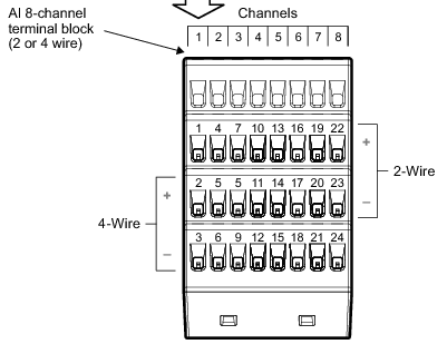
2 6 3 7 measuring current including 4 20 ma with a resistive. Type 4 refers to a 4 wire transmitter where the transmitter and receiver float and separate power leads power the transmitter outside of the current loop. Several transmitter wiring options exist.
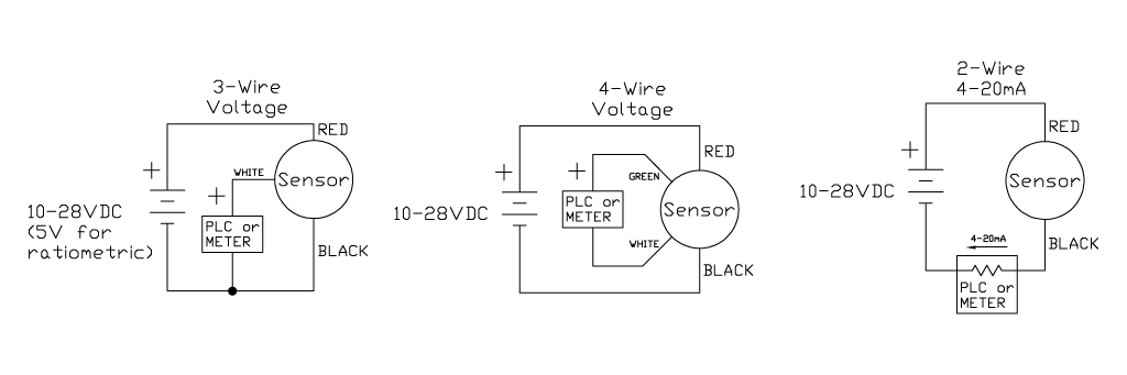
Diagram 2 3 4 wire transmitter working principle and related problemstwo wire system three wire system four wire system refers to the output of a variety of analog dc current signal transmitter its working principle and structure of the difference rather than just refers to the transmitter wiring form. The schematic diagram below shows the wire transmitter configuration. 4 20ma pressure transducer wiring diagram elegant viatran model.
In fact 24vac is a common power voltage for ac powered 4 wire transmitters. 3 phase fan wiring wire center. 4 wire transmitter of a graphic i get from the pressure transducer wiring diagram package.
The commons are connected together on the data logger. Instead a 2 wire transmitters circuitry is designed to act as a current regulator limiting current in the series loop to a value representing the process measurement while relying on a remote source of power to motivate current to flow. You can save this photographic file to your personal device.
4 wire transmitter wiring diagram collections of 3 wire pressure transducer wiring diagram wiring diagram collection. Check with the transmitter manufacturers to see that this. The power supply and the instruments are usually mounted in the control room.
4 3 2 output 4 20ma 1 output 4 20ma 120vac power 120vac power dc power supply transmitter 2 wire transmitter 2 wire 25 ma common 25 ma 25 ma common 25 ma 25 ma common 25 ma 25 ma common 7 7 6 5 4 3 2 1 output 4 20ma 4 20ma note. These wiring options include. 4 wire pressure transducer wiring diagram ge ac blower motor wiring diagram ge ac blower motor wiring diagram ac blower motor wiring diagram free chevy general electric furnace wiring diagram wiring diagrams air conditioner wiring diagrams allison transmission speed sensor wire schematic illustrations allison md transmission 1.
We also have some more images associated to pressure transducer wiring diagram please see the picture gallery below click one of the.
 Emerson Exchange 365
![]() Pressure Transmitter Wiring Diagram New 4 Wire Pressure Transducer
Pressure Transmitter Wiring Diagram New 4 Wire Pressure Transducer
![]() 7 Loop Powered Signal Isolator Wiring Diagrams Ato Com
7 Loop Powered Signal Isolator Wiring Diagrams Ato Com

 Transmitter Wiring Diagram Schematic Diagram Data
 4 Wire Mass Flow Meter Wiring Connection Detail In Hindi
![]() 2wire Rtd Diagram Wiring Diagram G8
2wire Rtd Diagram Wiring Diagram G8
![]() 3 Wire 4 20ma Wiring Diagram Schematic Wiring Diagrams Mon
3 Wire 4 20ma Wiring Diagram Schematic Wiring Diagrams Mon
The Basics Plcdesign
 4 To 20 Ma Current Loop Output Signal
 Wiring Diagram 2006 39 Chevy Tps 4 Wires Wiring Diagram

 4 Wire Transmitter Wiring Diagram Diagram Data Schema Exp
![]() 7 Loop Powered Signal Isolator Wiring Diagrams Ato Com
7 Loop Powered Signal Isolator Wiring Diagrams Ato Com
 Basics Of The 4 20ma Current Loop Learning Instrumentation And
![]() Basics Of Two Three Four Wire Transmitters Instrumentation Tools
Basics Of Two Three Four Wire Transmitters Instrumentation Tools
 Back To Basics Loop Vs Line Power Precision Digital
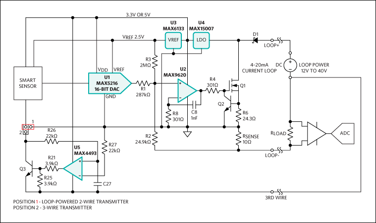 High Accuracy 4 20ma Current Loop Transmitter
4 20ma Wiring Diagram Wiring Diagram
 4 20 Ma Current Loops Assembling The Dc Power Supply Panel A


 What Is The Difference Between Two Wire And Four Wire Transmitter
![]() Pt100 Wiring Diagram Wiring Diagram
Pt100 Wiring Diagram Wiring Diagram
 554891 Wiring Examples For 2080 If4 Module
![]() Pressure Transmitters Wire Configuration Learning Instrumentation
Pressure Transmitters Wire Configuration Learning Instrumentation
0 Response to "4 Wire Transmitter Wiring Diagram"
Post a Comment