Baldor Electric Motors Wiring Diagram
A wiring diagram is a simple visual representation from the physical connections and physical layout associated with an electrical system or circuit. The drawing for the product you have selected is available from our part community portal.

The other 9 wires would be connected as in a 9 wire motor note in a 9 wire motor the equivalent of t10 t11 and t12 are internally connected together.

Baldor electric motors wiring diagram. Baldor motor capacitor wiring diagram what is a wiring diagram. A wiring diagram is a straightforward visual representation from the physical connections and physical layout of an electrical system or circuit. On a 12 wire motor wired for high voltage ie 480v 10t 11t and 12t must be connected together but not connected to anything else.
A wiring diagram is a simplified conventional photographic depiction of an electrical circuit. It shows how the electrical wires are interconnected and will also show where fixtures and components could possibly be coupled to the system. Baldor motors wiring diagram variety of baldor motors wiring diagram.
If not the arrangement will not function as it should be. You need to refer to the individual plate for your particular electric motor when wiring it as wiring procedures may be different particularly between ac and dc motors. It reveals the parts of the circuit as simplified shapes as well as the power and also signal connections between the tools.
It shows the elements of the circuit as streamlined shapes as well as the power and signal links in between the tools. For additional service please contact a local sales office. Baldor motor wiring diagram baldor 5hp motor wiring diagram baldor brake motor wiring diagram baldor dc motor wiring diagram every electrical structure is composed of various diverse parts.
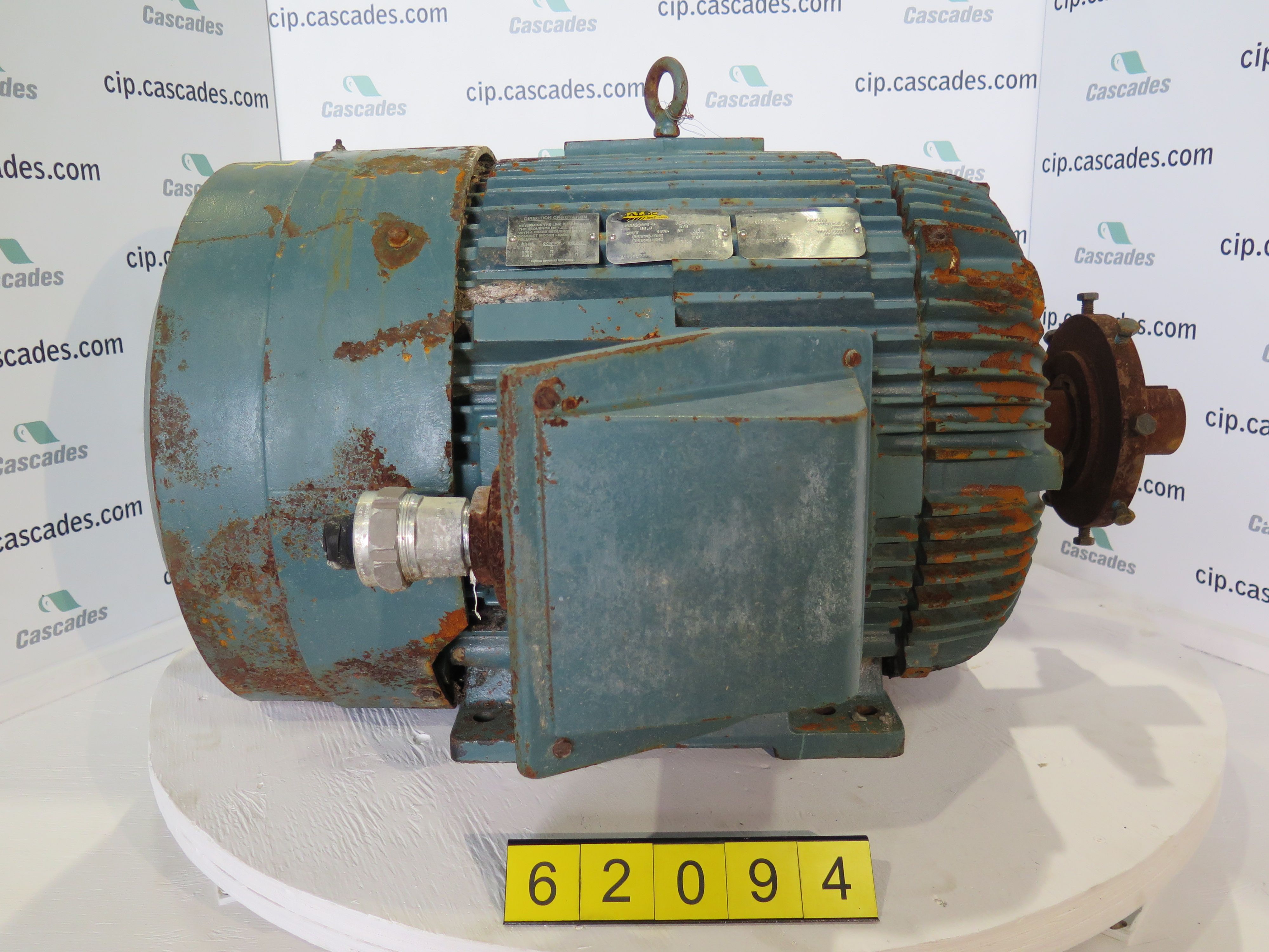
A wiring diagram is a streamlined traditional photographic depiction of an electrical circuit. Each type of baldor electric motor has labeled wiring diagrams on a plate fixed on the motor. Visit our portal by following the link below.
Each component should be set and connected with different parts in particular way. Baldor motors wiring diagram what is a wiring diagram. Baldor single phase motor wiring diagram collection of baldor single phase motor wiring diagram.
 100 Hp Baldor Motor Wiring Data Wiring Diagram


 Baldor Wiring Diagram Electric Motor Fresh Inspiration For Simple
 Baldor 220 Volt Wiring Diagram Wiring Diagram And Electrical Schematic
 Motor Capacitor Wiring Diagram Wirings Diagram

 Baldor 3hp Single Phase Motor Wiring Diagram Bestharleylinks Info

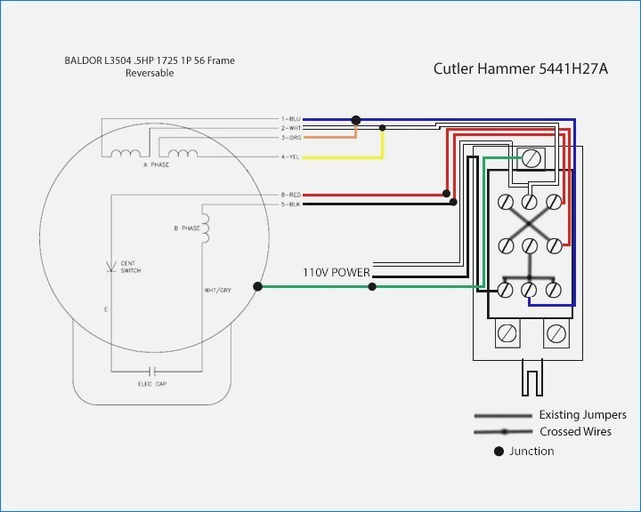
 Baldor Single Phase 230v Motor Wiring Diagram Gallery Wiring

 Baldor Single Phase Motor Wiring
 Baldor Electric Motor Capacitor Wiring Wiring Diagram And

 Baldor 3 Phase Motor Wiring Diagram Baldor Electric Motor Capacitor

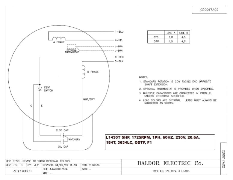
 Get Baldor 5hp Motor Wiring Diagram Sample

 Baldor Reliance Industrial Motor Wiring Diagram Easy Baldor Motor


 Baldor L1410t Capacitor Wiring Diagram Wiring Diagrams My
 Ge Single Phase Motor Wiring Diagram Free Wiring Diagram
 Https Www Airspringsoftware Com 1969 12 31t18 00 00 00 00 Hourly


0 Response to "Baldor Electric Motors Wiring Diagram"
Post a Comment