Consider The Circuit In The Diagram Below In Which R 11 ω
Consider the circuit shown in the diagram below for r1 5 ω r2 8 ω r3 8 ω r4 8 ω and v0 80 v. Calculate the current through r4.
 Engineering Principles And Applications Of Electrical Engineering
A what is the resistance between points a and b.
Consider the circuit in the diagram below in which r 11 ω. Need help understanding how to do these problems thanks image url below a what is the equivalent resistance of the circuit shown below if r1 95 ω and r2 174 ω. By looking at the circuit you can see that all of this current must pass through r1 to return to the battery. Lr tc time constant 60m15k 40u seconds b.
Find a the time constant of the circuit and b the maximum charge on the capacitor. At what time has the current in the 11 ω resistor decayed to half the value it had immediately after the switch was closed. Consider the series lr circuit below.
For more chapter 18 physics problems go to. Assume r1 115 ω and r2 300 ω a find the potential difference between points a and b. R 3 100 v 250 v r 4 100 r 5 500 500 r 2 1 200 a b label the voltage v 250 v and the resistances clockwise from b r 1 200 r 2 500 r 3 100 r 4 100 and r 5 500.
Right now it looks like you have calculated the circuit current current through the battery. I 120 15k 80ma c. Consider the circuit shown in figure p2129.
Consider the circuit in the diagram in which r 11 ω. If this was a. Computing some equivalent resistance of r 1 and r.
What is the eventual steady state current with s1 closed. Findathe current in the r 1 20 resistor andbthe potential di erence between points aand b. ω b a 259 v emf is connected to the terminals a and b as shown above.
Yes you are definitely on the right track. R total 128 132 26 ohms next find the total current using ohms law. The link to the diagram can be found below consider the circuit shown in the figure below.
Consider the circuit shown in the figure below. Consider a series rc circuit as in the figure below for which r 100 mω c 500 µf and ε 300 v. To find the total resistance of the circuit simply add r1 to the equivalent parallel resistance of 128 ohms to get.
Consider the circuit in the figure below in which r 11 ω c 75 µf the capacitors are charged and the switch closes at t 0 s. R 190 ω a find the. What is the equivalent resistance of the circuit shown below if r1 95 ω and r2 174 ω.
What is the time constant of the circuit with s1 closed. I vr 12 26 462 amps. What is the value of the circuit current at the first instant s1 is closed.
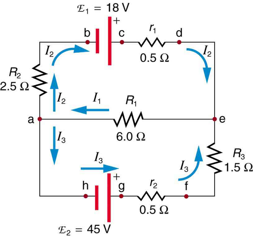 Kirchhoff S Rules Physics
 Parallel Resistors Electric Circuits Siyavula
 Node Voltage Method Article Khan Academy
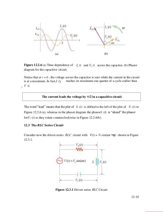 R L C Circuit
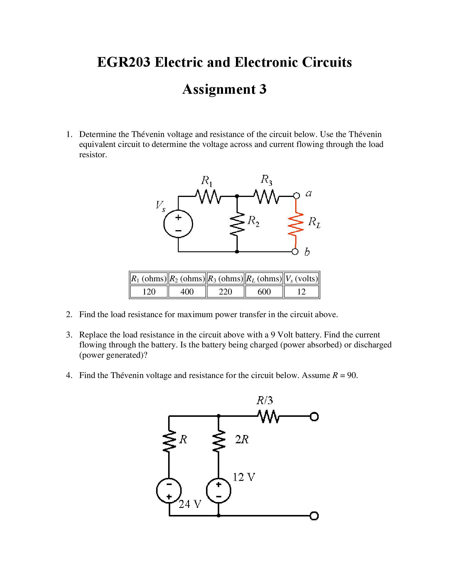 Solved Determine The Thevenin Voltage And Resistance Of T
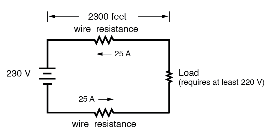 Specific Resistance Physics Of Conductors And Insulators
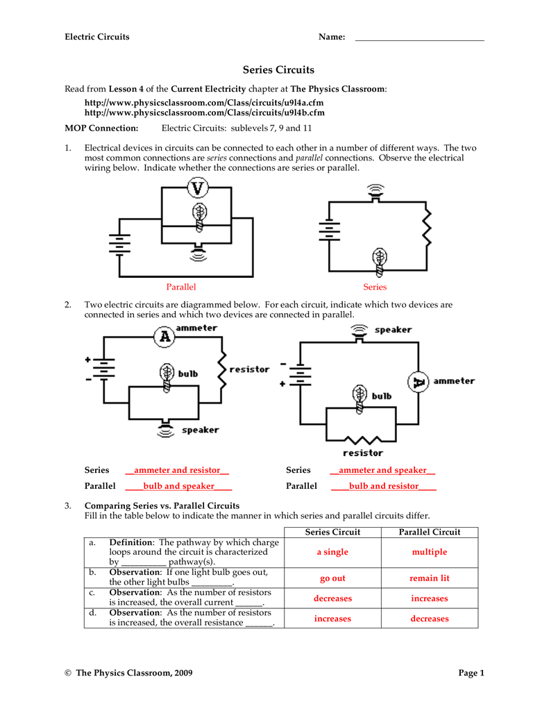 Series Circuits
Computer Setup
 Solved Consider The Circuit Shown In The Figure Below L
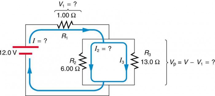
19 3 Parallel Circuits Texas Gateway
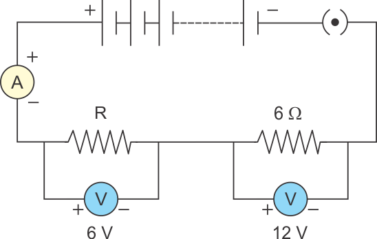
 Potential Difference And Resistor Voltage Division
 Find The Equivalent Resistance Between Points A And B Shown In The
19 3 Parallel Circuits Texas Gateway
 Ac Resistance And Impedance In An Ac Circuit
.jpg)
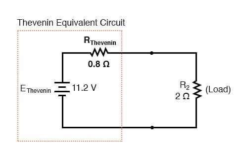 Thevenin Norton Equivalencies Dc Network Analysis Electronics
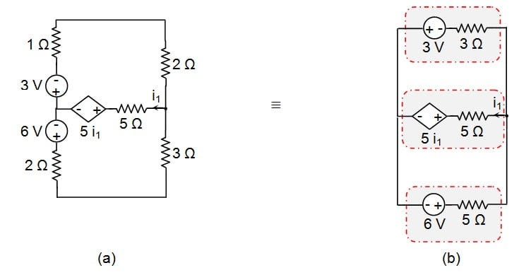 Analyzing Circuits Via Source Transformation
 Consider The Following Circuit Diagram If R1 R2 R3 R4 R5 3 Ohm
19 3 Parallel Circuits Texas Gateway
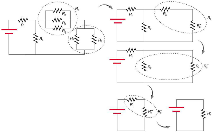
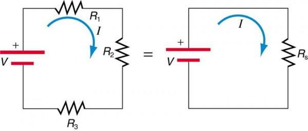
Resistors In Series And Parallel Physics
 Ap Physics 1 Review Of Charge And Circuits Video Khan Academy
19 3 Parallel Circuits Texas Gateway

 Resistors In Series And Parallel Physics
 Resistors In Series And Parallel Physics
Solving For Voltage And Current
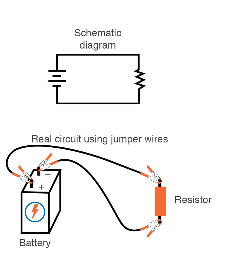 Building Simple Resistor Circuits Series And Parallel Circuits
0 Response to "Consider The Circuit In The Diagram Below In Which R 11 ω"
Post a Comment