Start Stop Wiring Diagram
I zl ii i i ii i i fo 0. 2 4 6 m 1 ol 3 phase motor a1 a2 remove wire c when it is supplied.

Connection diagrams or wiring diagrams show the components of the control circuit in a semblance of their actual physical locations.

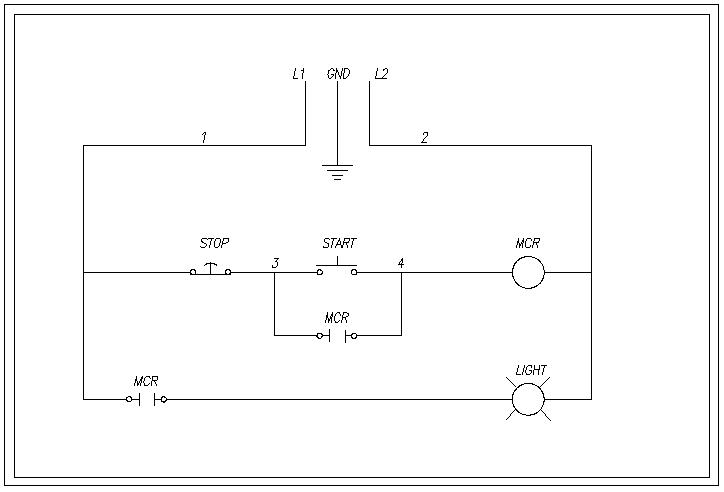
Start stop wiring diagram. The start stop push button station is shown more as an actual device in the control circuit wired to a set of contacts marked 2 and 3. The stops switch is normally closed. Push start button and contactor closes.
Connect separate control lines to the no. 1 j start 2 3 stop i no. It goes in series with contactor power and a normally open contact on the contactor.
In that case we would normally wire the start button using a normally open contact so pushing the start button turns the input on and we would wire the stop button using a normally closed contact so pushing the stop button turns the input off. Typical wiring diagrams for pushbutton control stations start stop control wiring diagrams single station basic circuit r 1 klai. In figure 14 the wires on each side of the m con.
Goggle contactor wiring diagram and multitude of images will come up. Figure 4 three wire control for jog or run using start stop push buttons and jog run selector switch. The most common use of 3 wire control is a startstop control.
Push stop button and contactor opens. Start stop station wiring diagram welcome to our site this is images about start stop station wiring diagram posted by benson fannie in start category on jun 08 2019. I operation depressing the start button energizes coil m hold in contacts m and maintains the circuit after the start button is released.
1 termi nal on the remote pilot device and the termi nal 96 on the overload relay. See image below for an example of 3 wire control being used to pull in a contactor to start a 3 phase motor. Improper wiring can kill injure start fires burn out motors or anyall of the above.
Normally open contacts can and do get welded in the on position sometimes. Figure 5 control for jog or run using stop push button and jog run selector push selector switch. Remote pilot devices 2 wire control 3 wire control.
Figure 3 three wire control giving low voltage protection with safe run selector switch. 3ph starter3ph motor line voltage control three phase 3ph motor starter controlling a three phase motor rev 08 aug 2006 the above wiring diagram assumes your magnetic starter has a 240v coil. You can also find other images like images wiring diagram images parts diagram images replacement parts images electrical diagram images repair manuals images engine diagram images engine scheme diagram images wiring.
When you press the start button and the stop button is not pressed the 24vdc relay energizes and it pulls in the r1 contactor that feeds three phase power to the motor. Start stop 3 2 1 1 3 not for use with auto reset ol relays. No contact opens so contactor does close when stop is released.
 Onan 16 Hp Wiring Diagram Wiring Diagram Mega
 Contactors Wiring Diagram Pdf Wiring Diagram Experts
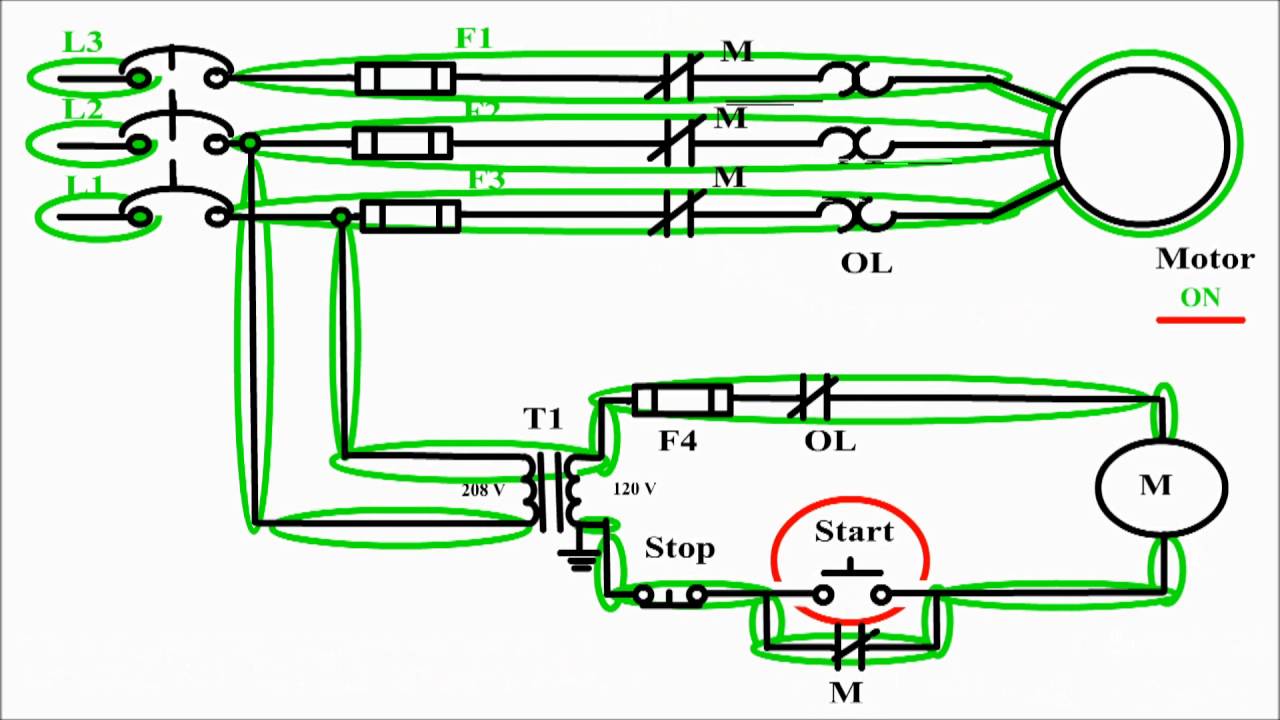 Motor Control Circuit Diagram Start Stop 3 Wire Control Youtube
 Control Wiring 3 Wire Control Start Stop Circuit
 Start Stop Push Button Wiring
 Start Stop Station Wiring Diagram Wiring Diagram Schematics
 1234 Wiring Diagram With Relay Wiring Diagram
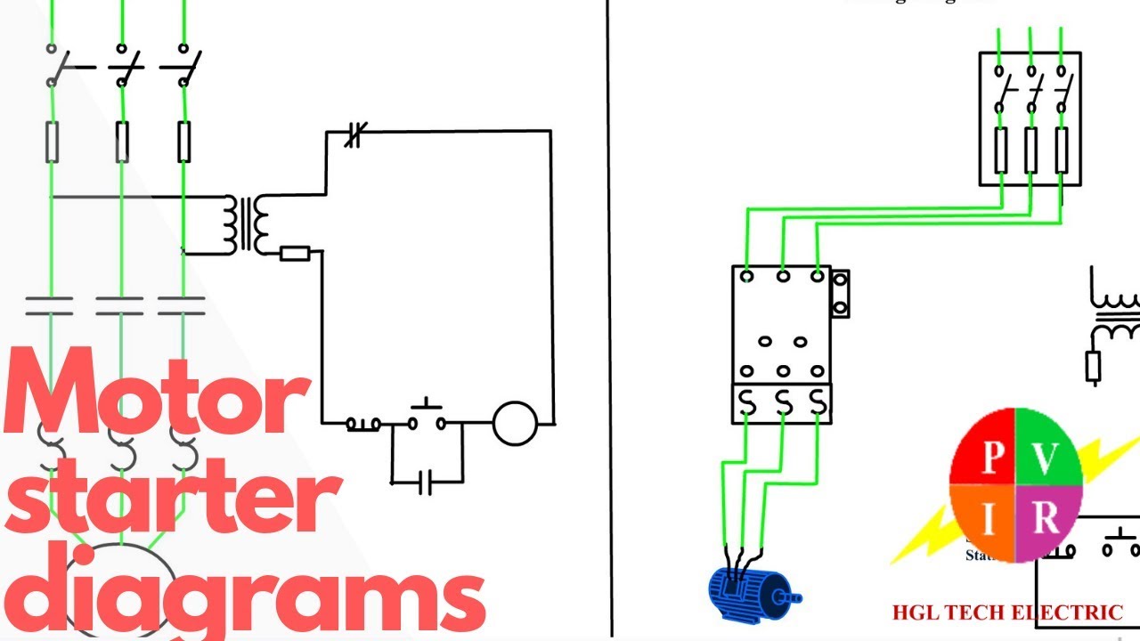 Motor Starter Diagram Start Stop 3 Wire Control Starting A Three
 Onan Wiring Diagram Wiring Diagram B7
 Simple Start Stop Wiring Diagram Wiring Diagram
 Lessons In Electric Circuits Volume Iii Semiconductors Chapter 7
 Wiring Diagram 700 434 Gas Valve Diagram Data Schema Exp

 Run Stop Relay Circuit
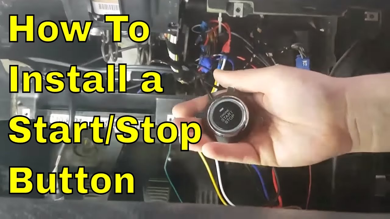 How To Install A Universal Engine Start Stop Button Youtube
 V Star 650 Wiring Diagram Wiring Diagrams
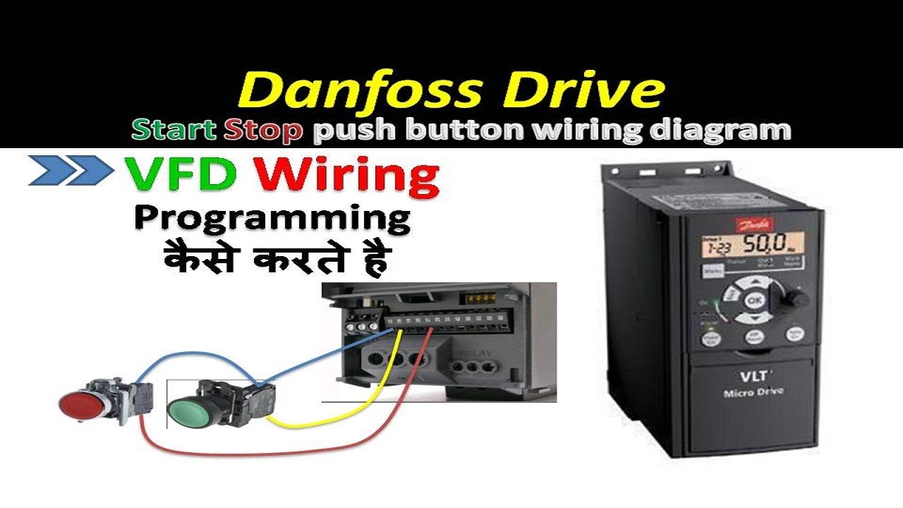 Vfd Motor Starter Wiring Schematic Wiring Diagram Tutorial
 3 Wire Start Stop Wiring Diagram Elec Eng World Electronics
 Basic Steps In Plc Programming For Beginners Eep
 2019 Keyless Entry System Car Start Stop Engine Auto Ignition
 Start Stop Schematic For Conveyor 2 Chime Doorbell Wiring Diagram

 Wiring Diagram Single Motor With Start Stop Switch Electrostudy
 Three Phase Plug Wiring Diagram Wiring Diagram
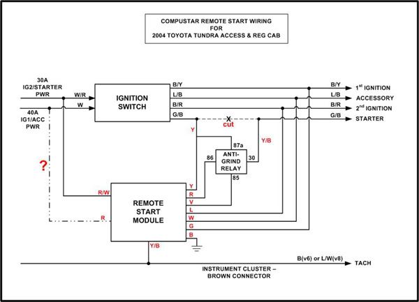
 Viper Remote Starter Installation Diagram Wiring Diagram
 Allen Bradley Motor Starter Wiring Diagram Wiring Diagram Official
0 Response to "Start Stop Wiring Diagram"
Post a Comment