Septic Pump Wiring Diagram
Electrical disconnect box for the grinder pump system. The ground wire from the panel will connect directly to the ground wire from the pump.
Septic Pump Septic Pump Septic Pump System Bethkroeker Com
Gfci and gfi wiring diagrams.
Septic pump wiring diagram. Step 4 press all the wiring into the junction box and screw the cover into place. Wiring a receptacle for a lift pump for a septic system. A wiring diagram is a streamlined conventional photographic depiction of an electrical circuit.
There will normally be separate wires for the pump controls. Sewage pump tank vent. It shows the components of the circuit as simplified shapes as well as the power as well as signal links between the tools.
Hold the bare ends of the black wires together and insert the pair into a wire nut twisting it until it is tight. It shows the parts of the circuit as simplified forms and also the power and also signal links between the devices. Septic pump float switch wiring diagram what is a wiring diagram.
The features and benefits of gfci outlets and receptacles will give you a clear understanding of the importance why these safety devices are required by code to help protect you and your family against accidental electrical shock hazards. Literally a circuit is the course that enables electrical energy to. Assortment of septic pump float switch wiring diagram.
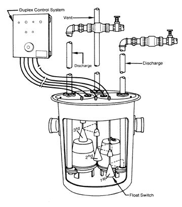
Repeat with the white wire and the other wire from the float switch. Route the plug wire from the septic tank pump up and out of the tank to the new electrical box. Electrical wiring leads for the grinder pump and septic pump alarm.
In 115v wiring you are dealing with 3 legs. A first take a look at a circuit representation might be complex yet if you can check out a metro map you can review schematics. The neutral wire from the panel will connect directly to the neutral wire from the pump.
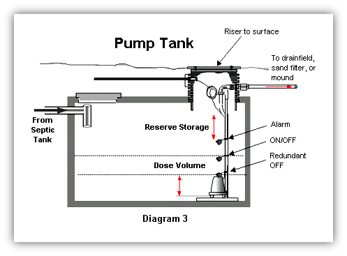
4 pvc tank inlet for connection to building drains served by the pump. A wiring diagram is an easy visual representation of the physical connections and physical layout associated with an electrical system or circuit. The pump will be controlled by a float or other switch which will activate the pump when the water reaches a pre set depth.
Septic pump float switch wiring diagram a novice s overview of circuit diagrams. A wiring diagram is a simplified traditional photographic representation of an electric circuit. Of the tank to a.
The sewage grinder tank must be vented either directly or through the inlet pipe and within 4 ft. The pump will have these three wires and the incoming power supply will have these three wires. Assortment of septic pump wiring diagram.
Obtaining from factor a to direct b. Hot neutral and ground.
Simplex Pump Wiring Diagrams Mcafeehelpsupports Com
Sewage Ejector Pump Installation Diagram Sewage Ejector Pit Sewage
Exterior Septic Pump Alarm Wiring Doityourself Com Community Forums
Goulds Septic Pump Well Wiring Diagram Awesome Pressure Switch Of 1
Septic Pump Wiring Diagram Wiring Diagram Schematics
 Sump Pump Control Wiring Diagram Fresh Septic Grinder Pumps
Submersible Sump Pump Diagram Submersible Sump Pump Submersible Sump
Pump Control Panel Wiring Diagram Me Content Uploads Septic Wiring
 Wiring A Septic Tank Wiring Diagram Schematics
 Septic Systems Repair Services Monticello Well Pump Services Inc
Ejector Pump Diagram Wiring Diagram Database
Bathroom Wiring Diagram Septic Pump Wiring Diagram Together With How
 Float Switch Installation Wiring Control Diagrams Apg
Pump Float Wiring Diagram Wiring Diagram Data Schema
 Septic Tank Pump Wiring Diagram Unsophisticated Aerobic Septic
 Ebara Pumps Wire Diagram Wiring Diagram Library
 Wiring Diagram For Residential Septic Pump Pores Fasett Info
 Septic Tank Wiring Schematic Wiring Diagram Schema
Simple Pump Wire Diagram Modern Well Pump Simple Fuel Pump Wiring
Welcome To My Site Iwiringdiagram Co Is A Wiring Diagram Great
 Septic Tank Wiring Diagram Data Wiring Diagram

Sewage Grinder Pump Wiring Diagram Wiring Diagram B7
 Septic Tank Installation Diagram Koran Sticken Co
Septic Pump Tank Diagram Septic Tanks Diagram Septic Tank Pump
 Septic Pump Relay Wiring Diagram My Wiring Diagram
 Float Switch Installation Wiring Control Diagrams Apg
Septic Pump Float Switch Wiring Diagram With Example Pics Diagrams
 Water Well Pump Control Box Septic Wiring Diagram Submersible Wire
0 Response to "Septic Pump Wiring Diagram"
Post a Comment