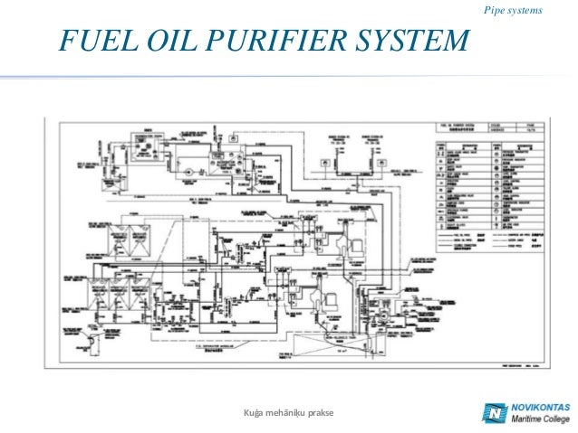
Fuel Oil Piping Diagram
This chapter shall govern the design installation construction and repair of fuel oil storage and piping systems. 13012 storage and piping systems.
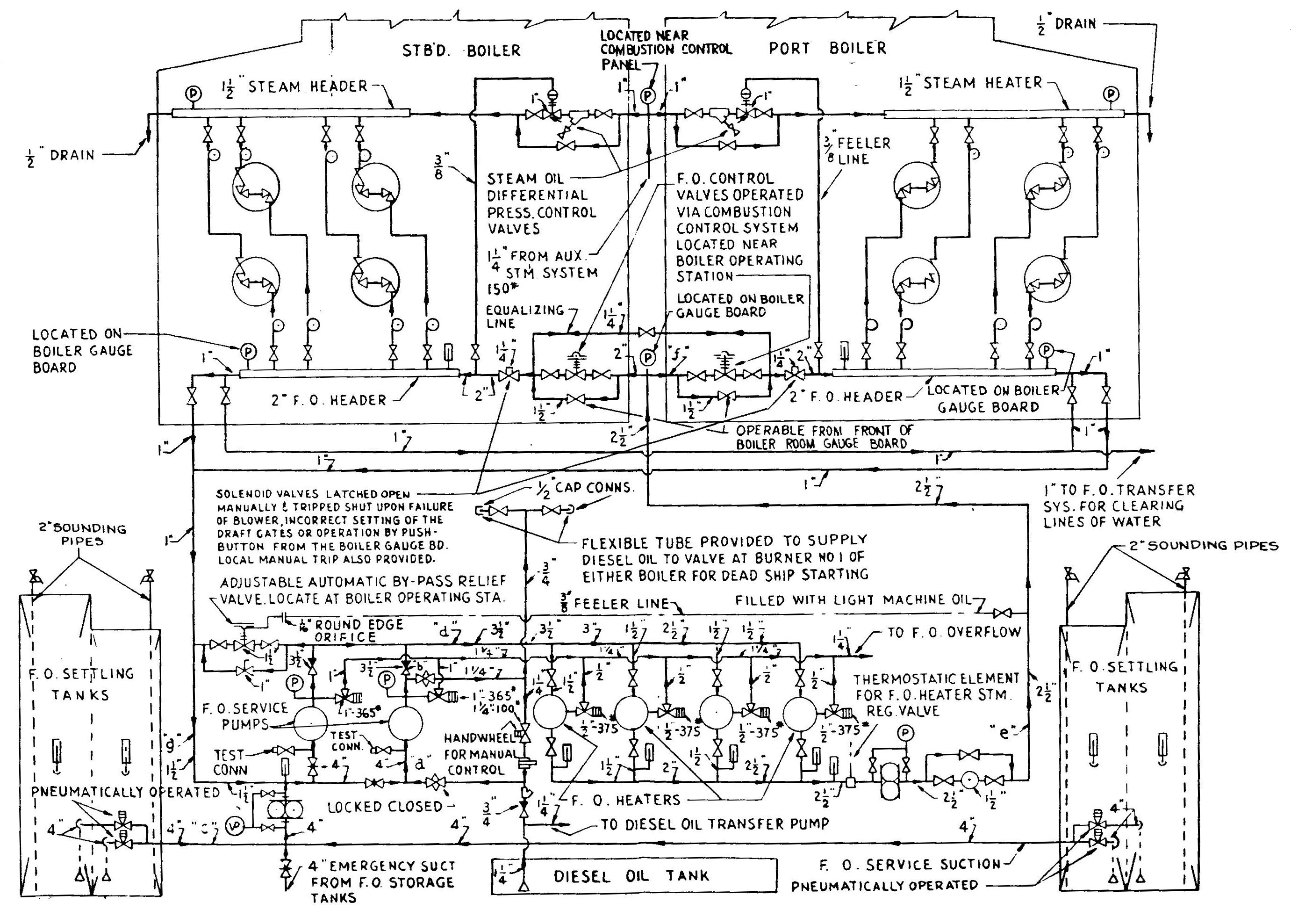
 Marine Piping Diagram Wiring Library
An engineering guide to modern fuel systems this publication is intended as a resource for designers installers and system operators.
Fuel oil piping diagram. This chapter shall apply to piping systems and their components used to transfer fuel oil from storage and supply tanks to oil burning appliances and equipment. 82 acceptable piping materials and piping system design. Oil tank fill vent piping guide.
But the regs and diagrams are informative. Fuel oil piping buried below ground. Chapter 13 fuel oil piping and storage section 1301 general 13011 scope.
If all oil returned by the burner or engine is returned to the day tank the fuel oil transfer system need only replace the fuel that is burned. I piping trench and pipe burial requirements important. Nfpa 31 fuel oil piping installation and testing chapter 8 fuel piping systems and components 81 scope.
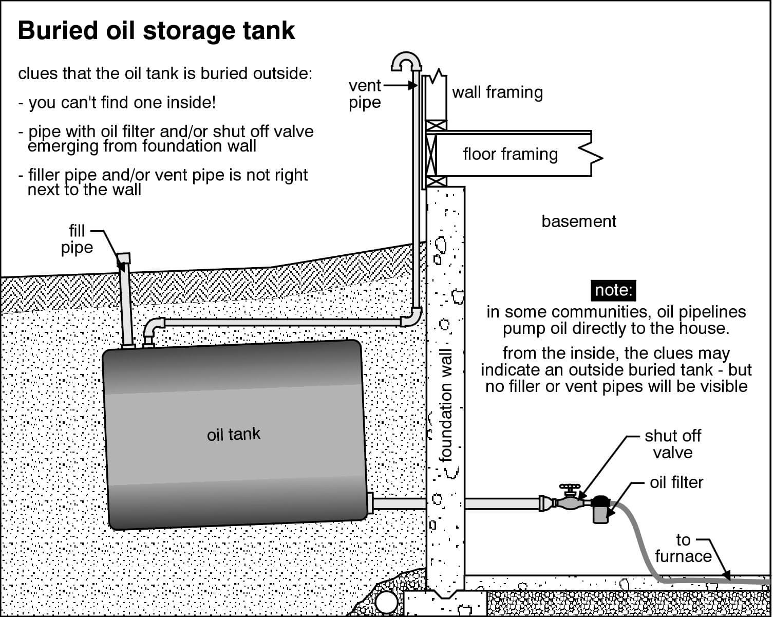
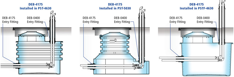
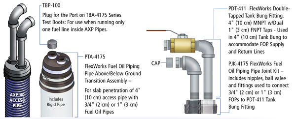
This heating oil piping article gives advice and example photos for the installation inspection leak troubleshooting of oil tank fill vent piping for both buried and above ground oil storage tanks. The recommendations of the engine manufacturer should always be followed with respect to fuel piping and cooling. All underground connections must be contained within a flexworks tank sump or transition sump see assembly diagrams on following pages.
Critical fuel systems division of bfs industries llc. In this document we highlight the typical indoor components and operational requirements of modern diesel fuel or fuel oil systems. Selecting the appropriate piping size for dual applications can be difficult.
The storage of fuel oil and flammable and combustible liquids shall be in accordance with chapters 6 and 57 of the international fire code. The fuel oil is pumped into the tug. The heated oil is returned to the main tank where it is diluted with cool oil.
Heating system oil burner by gravity flow. Fuel oil system piping diagram. 6 oil may be so big as to present priming problems when handling no.
Inspection for above ground heating oil storage tanks asts. Store fuel oil system components in a clean dry space and protect from the weather. Range day tank is filled by using the rotary hand pump.
There are a number of recommendations and regulations to be followed when installing an oil tank and its piping this type of install is classified as an indoor above ground installation as opposed to an outside or buried tank. Piping needed for fill pipe on fuel oil tank. Sump or through a concrete slab with a flexworks fuel oil pipe transition assembly pta 4175.
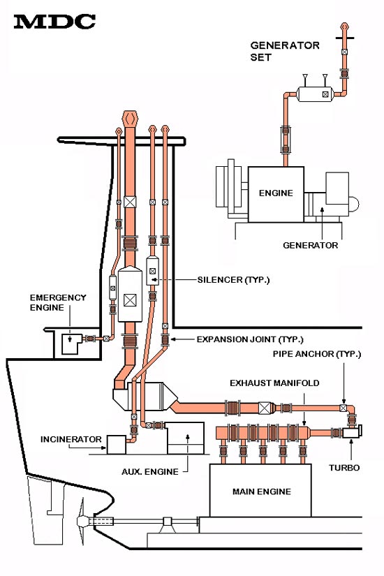
A suction line large enough to reduce the friction loss to an acceptable level for no. Propulsion engine the diesel auxiliary sets and the. Handle fuel oil system components carefully to avoid damage to material component enclosure and finish.
Part 2 products 21 pipe and fittings. Flexworks fuel oil piping systems must be. At the starboard side deck hose connection and using.
 The Change Of The Payback Period Depending On The Nominal Pipe Sizes
 Above Ground Tanks Pipe Schematic Storage Tanks Precautions To
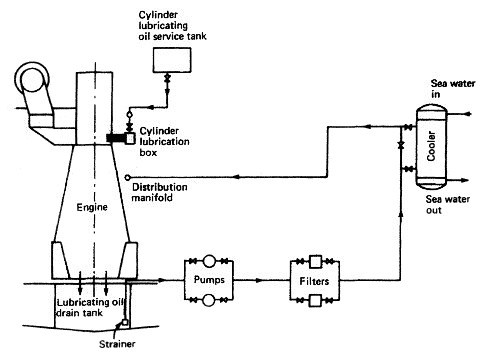
 Fuel System An Overview Sciencedirect Topics
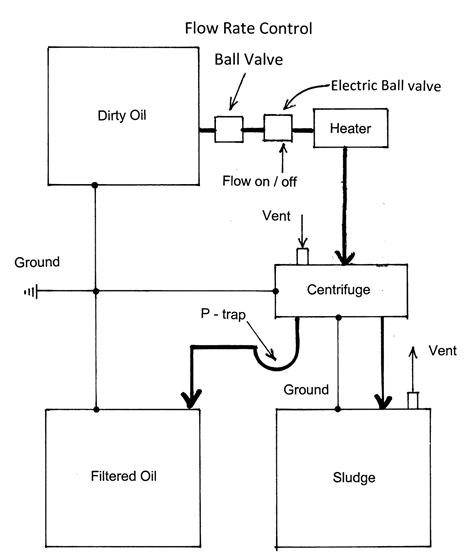 Centrifuge Piping Schematic Us Filtermaxx
 Pipe System
Tsps Engineering Manual
 How Does Water Get Into My Heating Oil Tank
Plant Engineering Data Indd
Fuel Oil System
 Fuel Oil Day Tank Piping Diagram Throughout Heating Oil Piping
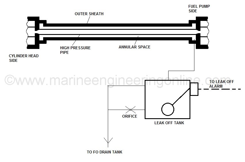
 A Better Way For Fuel Leak Detection In Secondary Containment Piping
 Piping Instrumentation Diagrams Guide Lucidchart

Job Number
 Remote Acting Fire Valve Commercial Fuel Solutions Ltd
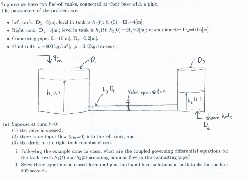 Solved Suppose We Have Two Fuel Oil Tanks Connected At T
Profire M
 Flexible Piping Systems For Fuel Oil And Generator Applications
 Effect Of Insulation Thickness On Energy Saving For Different
 Piping Diagram 2 Oil Tanks Wiring Diagram Schematics
0 Response to "Fuel Oil Piping Diagram"
Post a Comment