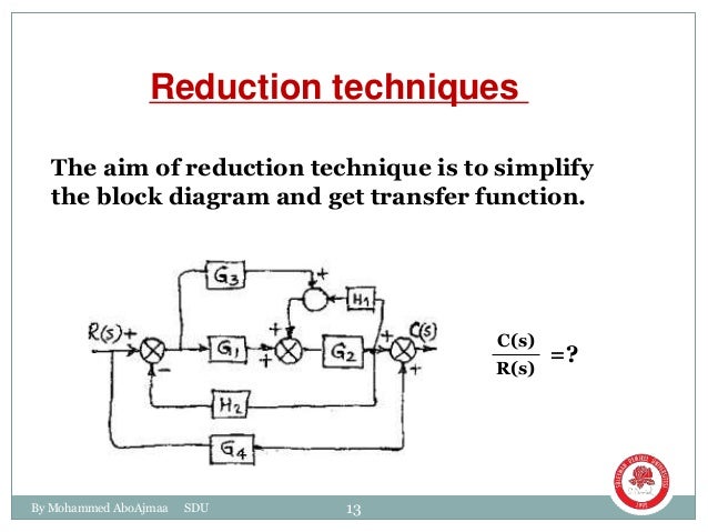
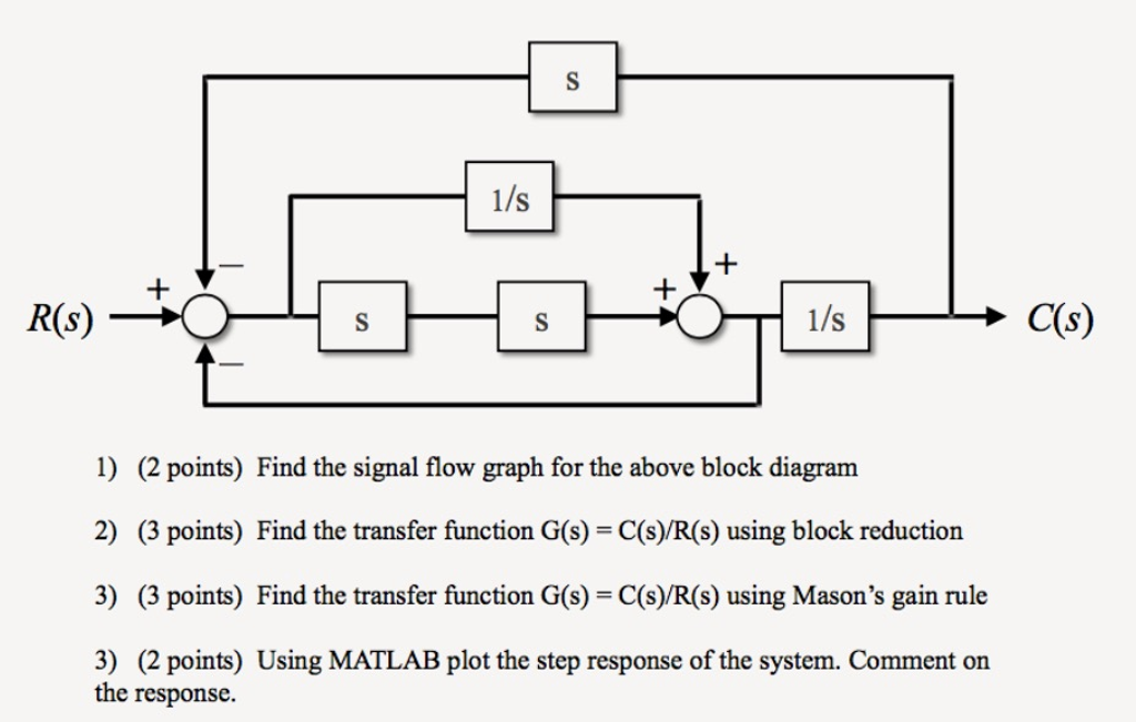
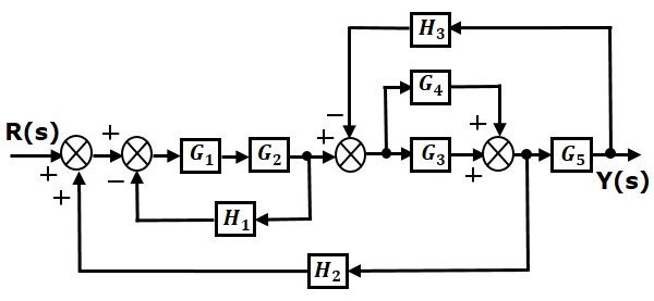
Block Diagram To Transfer Function
This command loads the functions required for computing laplace and inverse laplace transforms. Transfer function of linear time invariant lti systems 3.
Open Loop Transfer Function Block Diagram Awesome Avian S Blog
Block diagrams feedback and transient response specifications.

Block diagram to transfer function. Transfer functions in block diagrams. The first step in creating a transfer function is to convert each term of a differential equation with a laplace transform as shown in the table of laplace transforms. This module introduces the concepts of system block diagrams feedback control and transient response specifications which are essential concepts for control design and analysis.
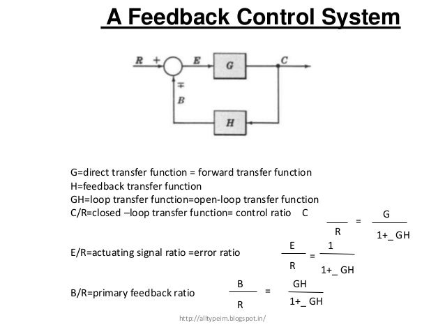
A transfer function g s relates an input u s to an output y s. Derive your closed loop transfer function given a block diagram. A control system may consist of a number of components.
A pictorial representation of the functions performed by each component and of the flow of signals. O summing points. Basic elements of block diagram.
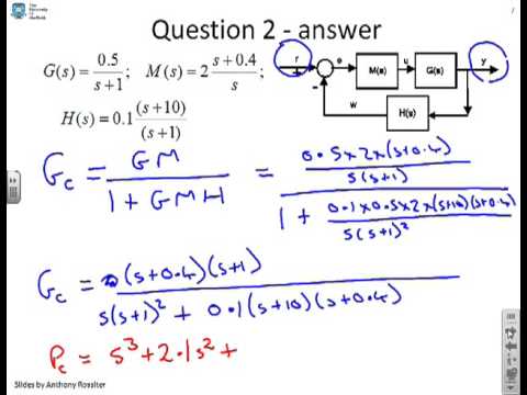
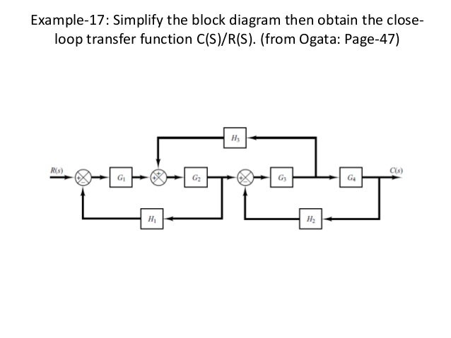
Let us now discuss these elements one by one. Time response analysis with matlab. Example problem on how to derive closed loop transfer function from block diagram.
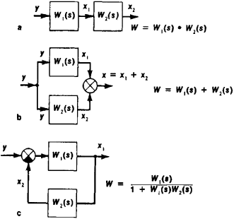
The above block diagram consists of two blocks having transfer functions g s and h s. Transfer functions and block diagrams 1. If we have two systems ft and gt we can put them in series with one another so that the output of system ft is the input to system gt.
It is also having one summing point and one take off point. When two or more systems are in series they can be combined into a single representative system with a transfer function that is the product of the individual systems. Arrows indicate the direction of the flow of signals.
Transfer functions with matlab 6. Basic elements of a block diagram. Introduction an important step in the analysis and design of control systems is the mathematical modelling of the controlled process.
O take off points. O transfer functions of elements inside the blocks.
 Block Diagram For Control Systems
 Block Diagram Transfer Function Rules Diagram Data Schema Exp
 Block Diagrams Of Control System Electrical4u
![]() Block Diagrams And Their Transfer Functions For The Exact
Block Diagrams And Their Transfer Functions For The Exact
![]() Block Diagram Of Transfer Function Rules Block Diagram Transfer
Block Diagram Of Transfer Function Rules Block Diagram Transfer

 Block Diagram Transfer Function Rules Diagram Data Schema Exp
 Block Diagram
Rules To Reduce Block Diagrams Transfer Function Problem Solving
 Block Diagrams 8 Tutorial Sheet On Closed Loop Transfer Functions
 Control System Getting Transfer Function From Block Diagram
 Figure 2 From A Method Of Transfer Functions And Block Diagrams To
 Block Diagram Examples
 Block Diagram Automatic Control Article About Block Diagram

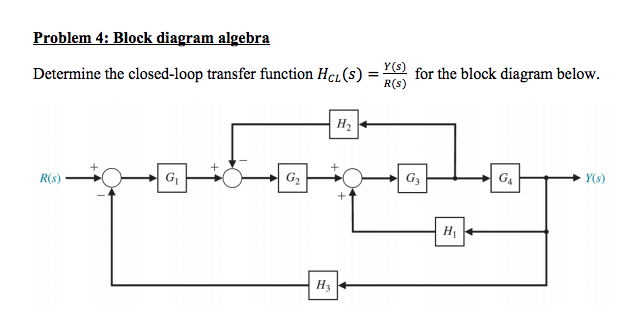 Solved Problem 4 Block Diagram Algebra Determine The Clo
 Given A Closed Loop Block Diagram Generate The Closed Loop Z
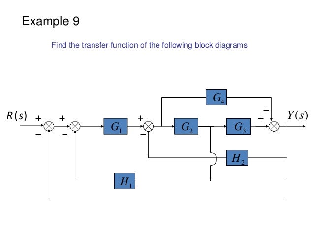
 Transfer Function Of Block Diagrams Exercise 1
 Block Diagram Examples
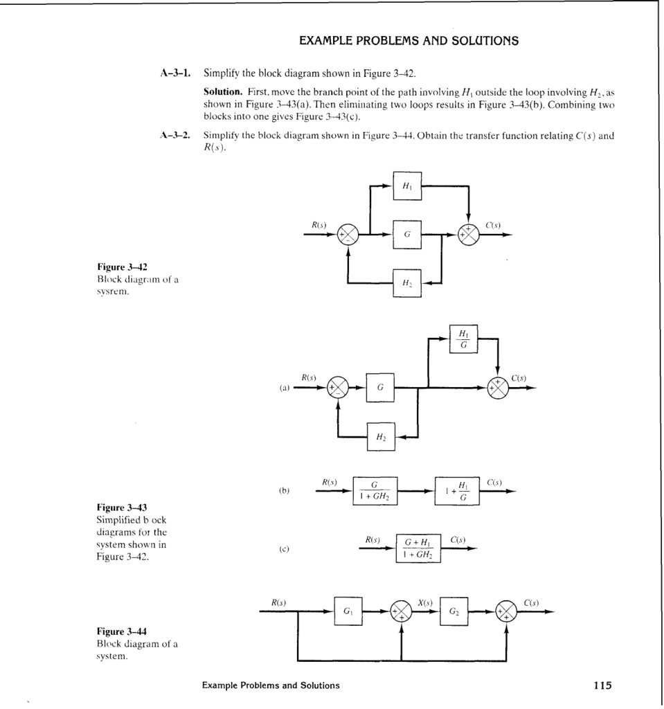 Example Problems And Solutions
 Solved Find The Transfer Function For The Block Diagram S
0 Response to "Block Diagram To Transfer Function"
Post a Comment