Phase Lock Loop Block Diagram
Block diagram of phase lock loop 5. Need of phase lock loop 4.
 Basic Introduction Of Phase Locked Loop Pll Sharing Is Loving
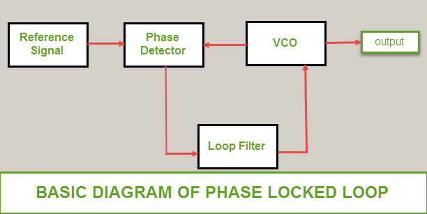
Basic diagram of phase locked loop block diagram and working principle of pll.

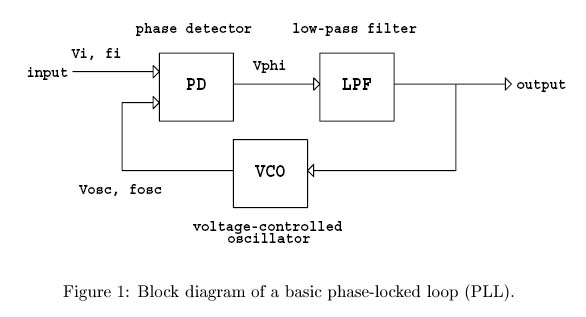
Phase lock loop block diagram. The phase locked loop consists of a phase detector a voltage control oscillator and in between them a low pass filter is fixed. The phase locked loop or pll is an electronic circuit with a voltage controlled oscillator whose output frequency is continuously adjusted according to the input signals frequency. In this video i have explained phase lock loop by following outlines.
The input signal vi with an input frequency fi is conceded by a phase detector. The phase locked loop or pll is a particularly useful circuit block that is widely used in radio frequency or wireless applications. A non integer multiple of the reference frequency can also be.
Phase locked loops pll introduction to pll. The concept of phase locked loops pll first emerged in the early 1930âsbut the technology was not developed as it now the cost factor for developing this technology was very high. Phase locked loop block diagram.
4 cd4046b phase locked loop. There are several different types. What is phase locked loop.
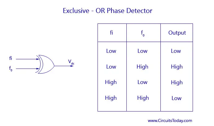
It may also have a divider in the feedback path or in the reference path or both in order to make the plls output signal frequency a rational multiple of the reference frequency. Phase lock loop 2. A digital phase locked loop uses a digital phase detector.
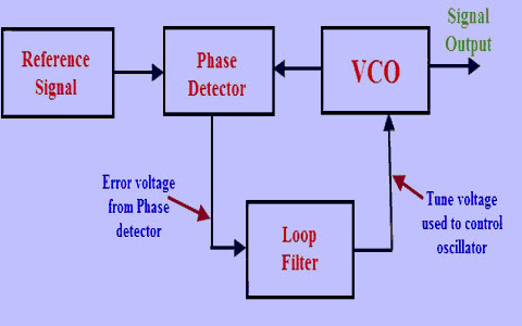
The simplest is an electronic circuit consisting of a variable frequency oscillator and a phase detector in a feedback loopthe oscillator generates a periodic signal and the phase detector compares the. They also lock the output phase to the input phase as you would expect from the name phase locked loop but its a different sort of lock the locking action is made possible by negative feedback ie by routing the output signal back to the phase detector as shown in the above diagram. Actually lots of engaging images in cyberspace concur block diagram phase locked loop.
Basics of phase lock loop 3. In view of its usefulness the phase locked loop or pll is found in many wireless radio and general electronic items from mobile phones to broadcast radios televisions to wi fi routers walkie talkie radios to professional communications systems and vey much more. A phase locked loop or phase lock loop pll is a control system that generates an output signal whose phase is related to the phase of an input signal.
A versatile building block for micropower digital and analog applications 3 cd4046b pll technical description figure 2 shows a block diagram of the cd4046b which has been implemented on a single monolithic integrated circuit. I am categorically glad to comprehensive block diagram phase locked loop and finally i upload it on this website. The pll structure consists of a low power linear vco and two.
I wish you are satisfied in the same way as the image i uploaded upon this website hopefully it can be useful for you. A phase locked loop is used for tracking phase and frequency of the input signal. It is a very useful device for synchronous communication.


 Phase Locked Loop Pll In A Software Defined Radio Sdr Wireless Pi

Introduction
 Figure 3 From Phase Locked Loop With Adaptive Signal Cancellation
 Describe The Basic Block Diagram Of The Phase Locked Loop Pll
 Phase Lock Loop Abisceg
 Delay Locked Loop Ip Faststream Technologies
 Phase Locked Loop Block Diagram Download Scientific Diagram
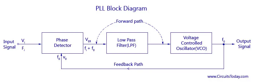

 Figure 2 From Stability And Resolution Analysis Of A Phase Locked
 Phase Locked Loop Pll Fundamentals Analog Devices
 Phase Locked Loop Operating Principle And Applications
 10 Block Diagram Of Phase Locked Loop Algorithm Download
 Pll Phase Locked Loop How It Works Electronics Notes
 Block Diagram Phase Locked Loop Mycircuits9
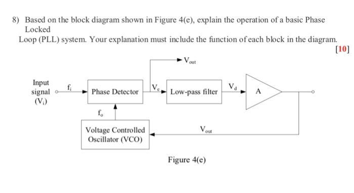 Solved 8 Based On The Block Diagram Shown In Figure 4 E
The Operation Of The Phase Locked Loop A Phase Locked Loop
 Demo Phase Locked Loop
Dpll Description Pdf 1 8v 1 Ghz Digital Phase Locked Loop Dpll Ali
 Principle Block Diagram Of Phase Locked Loop Download Scientific
 Phase Locked Loop Operating Principle And Applications

0 Response to "Phase Lock Loop Block Diagram"
Post a Comment