Air Ride Setup Diagram
Air suspension installation and air bag instruction manuals to help you install or replace your air ride parts. Tow assist wiring and plumbing diagram.

I am pleased with the quality of the products included in the kit.

Air ride setup diagram. Either rotate the sensor slight ly or adjust the linkage so that there is about 14 of clearance between the upper plastic stop and the rotating arm. Details of how to wire up a compressor for a bagged truck. This is what air ride technologies has done in its new levelpro system.
With 14 gauge primary wire from second terminal on pressure swirch to small switched terminal on top of the solenoid or terminal 85 on relay. Using switch wiring diagram run wires from assigned valves to switches with each valve solenoad being grounded at valve location. You can also find other images like images wiring diagram images parts diagram images replacement parts images electrical diagram images repair manuals images engine diagram images engine scheme diagram images wiring harness diagram images.
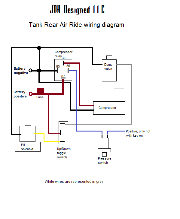
Tow assist wiring and plumbing diagram no tow kit. Tow assist tank wiring plumbing diagram. Air ride diagram thank you for visiting our site this is images about air ride diagram posted by maria rodriquez in air category on may 16 2019.
Almost all my videos are made my iphone4 that includes pictures videos credits adding music voice overs and editing. There are not many good pictures or videos to explain what to do. This is slowing.
Tow assist afc valves dual zone tank wiring plumbing diagram. Thank you for. To save money initially the setup can first be configured as a pressure based system only and the ride height sensors can.
Step 8 with the vehicle at the very bottom of the travel hold the sensor at the same location traced on the frame in step 7. Air suspensions and air ride instruction manuals for air ride compressors air suspension valves air ride bags and air reservoir tanks.
 Air Ride Plumbing Diagram Licensed Hvac And Plumbing
 Test Setup For Air Suspension System 1 Vertical Actuator 2
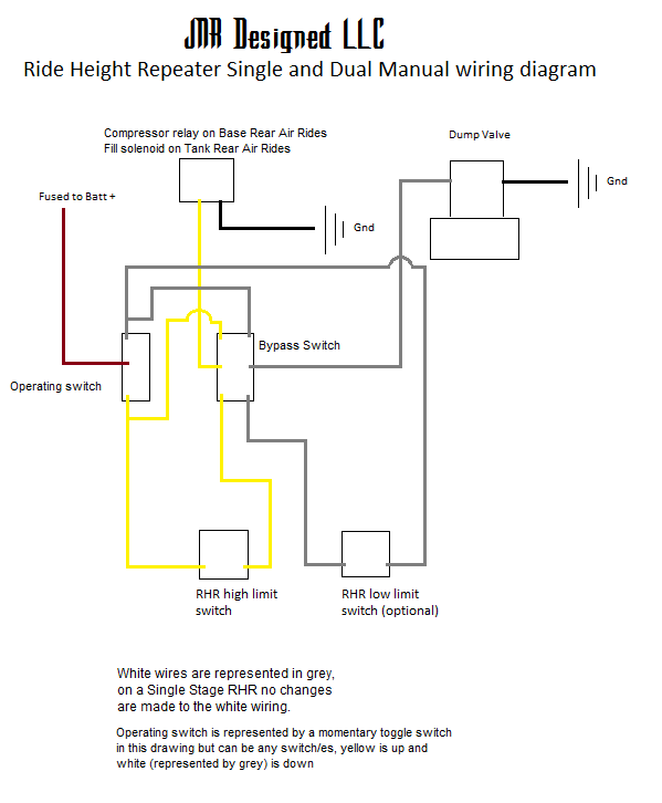 Ride Height Repeater Rhr Jnr Designed
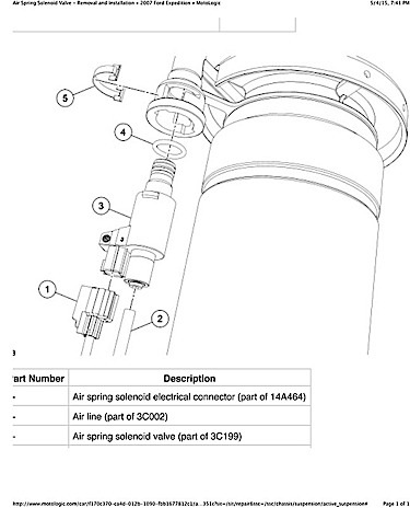
 Arnott Motorcycle Air Suspension
 Firestone Air Bags Ride Rite Air Spring Kits For Pickups

Mrp Ramp Control Cartridge
 Test Setup For Air Suspension System 1 Vertical Actuator 2
 Mountain Bike Suspension Basics Rei Expert Advice

 Air Ride Diagram Wiring Schematic Diagram 166 Pandoracharms Co

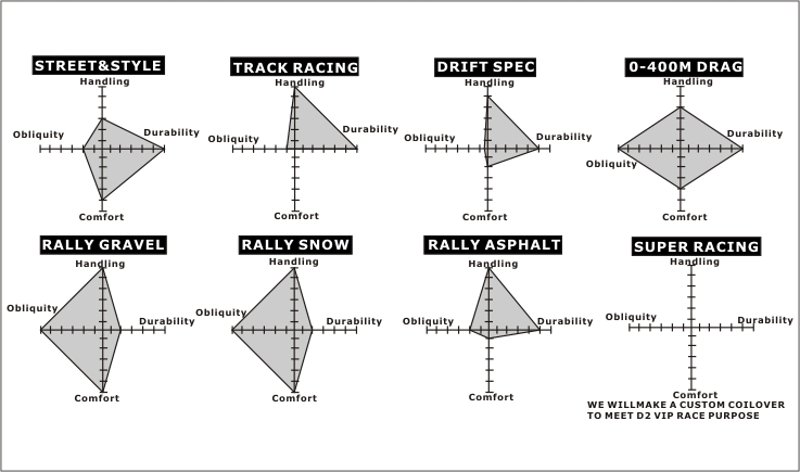 Coilover Technical Manual D2racingsport Eu


 Hadley Height Control Valves Powerdown Powerdown
 Accuair Vu4 Paddle Valve Air Ride Diagram Management Systems D2
Air Ride Suspension Diagram Wiring Diagram Schematics
 Wiring Diagram For Air Bag Suspension Wiring Diagram Schematics


 How To Install Air Ride Suspension Yourmechanic Advice
Air Lift Performance 3h 3p
 Air Bag Suspension Installation Air Ride Instruction Manuals Air

 How To Install Air Ride Suspension Yourmechanic Advice


Ksport Airtech Air Suspension Owner S Manual
0 Response to "Air Ride Setup Diagram"
Post a Comment