Transfer Function From Block Diagram
Because we have to draw the partially simplified block diagram after each step. Gs forward path transfer function.

It is used to represent all types of systems.

Transfer function from block diagram. Step 3 get the overall transfer function by adding all those transfer functions. Let us now discuss these elements one by one. It is also having one summing point and one take off point.
Example problem on how to derive closed loop transfer function from block diagram. The transfer function of a component is represented by a block. Step 1 find the transfer function of block diagram by considering one input at a time and make the remaining inputs as zero.
Block diagram reduction technique. It is defined as the ratio of the laplace transform of the output variable to the laplace transform of the input variable with all zero initial conditions. Step 2 repeat step 1 for remaining inputs.
It can be used together with transfer functions. I am having trouble to define in matlab the transfer function of the following block diagram. Gc represents the controller which produces a signal fs g11 is in series with gc.
Ecm2105 control engineering. Because of their simplicity and versatility block diagrams are often used by control engineers to describe all types of systems. Transfer functions are compact representations of dynamic systems and the differential equations become algebraic expressions that can be manipulated or combined with other expressions.
Hs feed back path transfer function. Transfer function of block diagrams exercise 1 starting to study the way to find the transfer function of a block diagram in control systems you can find that you have to reduce by blocks until you have only one block to find the transfer function this is a bit complicated when you have a block diagram with many components. A block diagram can be used simply to represent the composition and interconnection of a system.
Transfer functions in block diagrams one source of transfer functions is from balance equations that relate inputs and outputs. The block diagram reduction process takes more time for complicated systems. Arrows indicate the direction of the flow of signals.
The above block diagram consists of two blocks having transfer functions gs and hs.
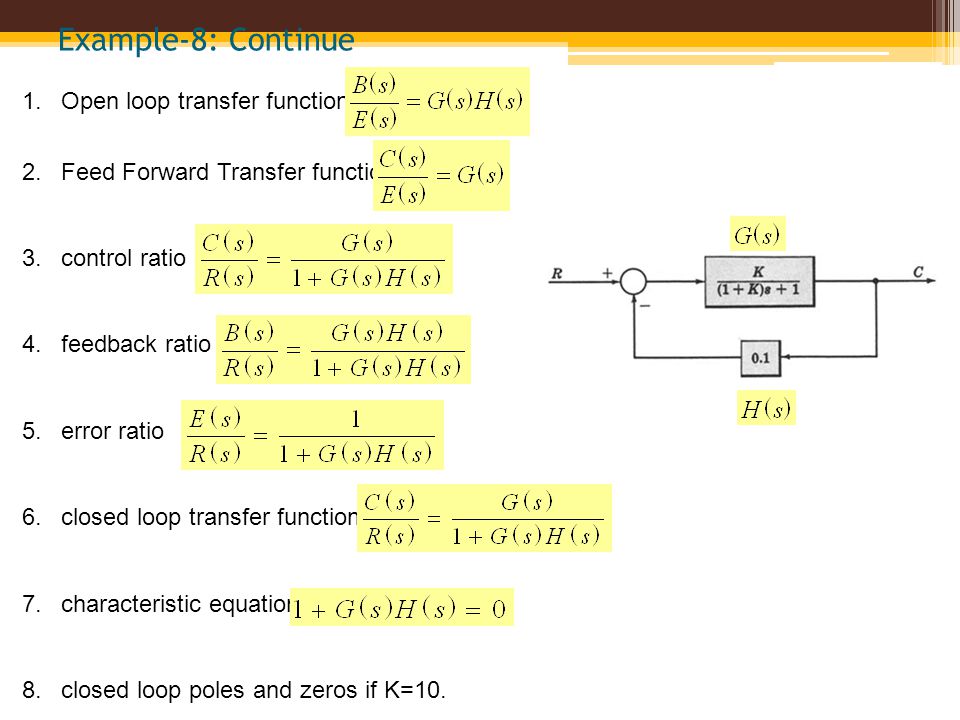 Block Diagram Fundamentals Reduction Techniques Ppt Video Online
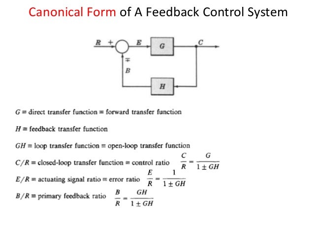 Lecture 8 9 Block Diagram Representation Of Control Systems
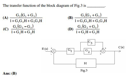 Solved The Transfer Function Of The Block Diagram Of Fig
Mathematical Models Block Diagrams
 Derive Transfer Function From Block Diagrams 2 Fe Eit Exam Youtube
 Block Diagram Representation Of Control Systems
Ebook Dynamic System Modeling And Control
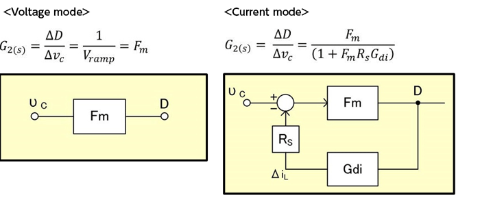 Slope Transfer Functions Summary Of Current Mode Transfer Functions
System Algebra And Block Diagram
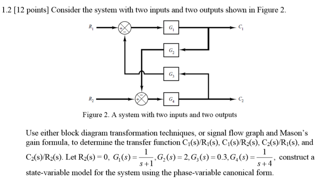 Block Diagram 2 Inputs Wiring Diagram
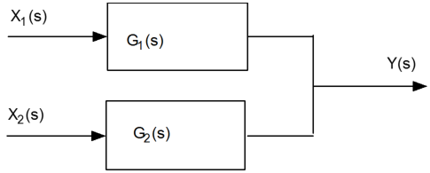 Transfer Functions In Block Diagrams Dynamics And Control
 Closed Loop System And Closed Loop Control Systems
 Transfer Function Block Diagram Pdf Block Wiring Diagram
 Block Diagram Integrator Wiring Diagram Data
Open Loop Transfer Function Block Diagram Awesome Avian S Blog
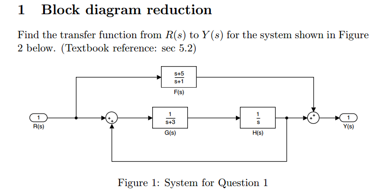 Block Diagram 1 S Wiring Diagram
 Transfer Function Block Diagram Reduction In Matlab Control Systems
H1 Align Center Enotes Mechatronics And Controls H1
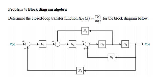 Solved Problem 4 Block Diagram Algebra Determine The Clo
 Wescott Design Services Using Block Diagrams
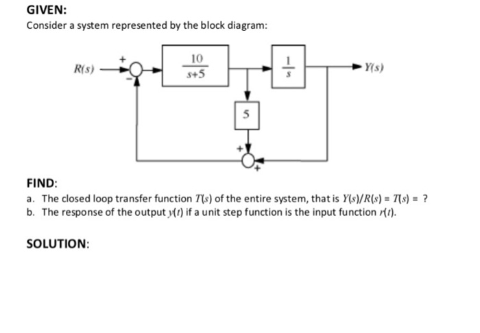
1 3 19 Find The Transfer Functions For The Block Diagrams In Fig
 Transfer Function Block Diagram Of Dc Motor Download Scientific
 Block Diagram Of Valve Control System Transfer Function Download
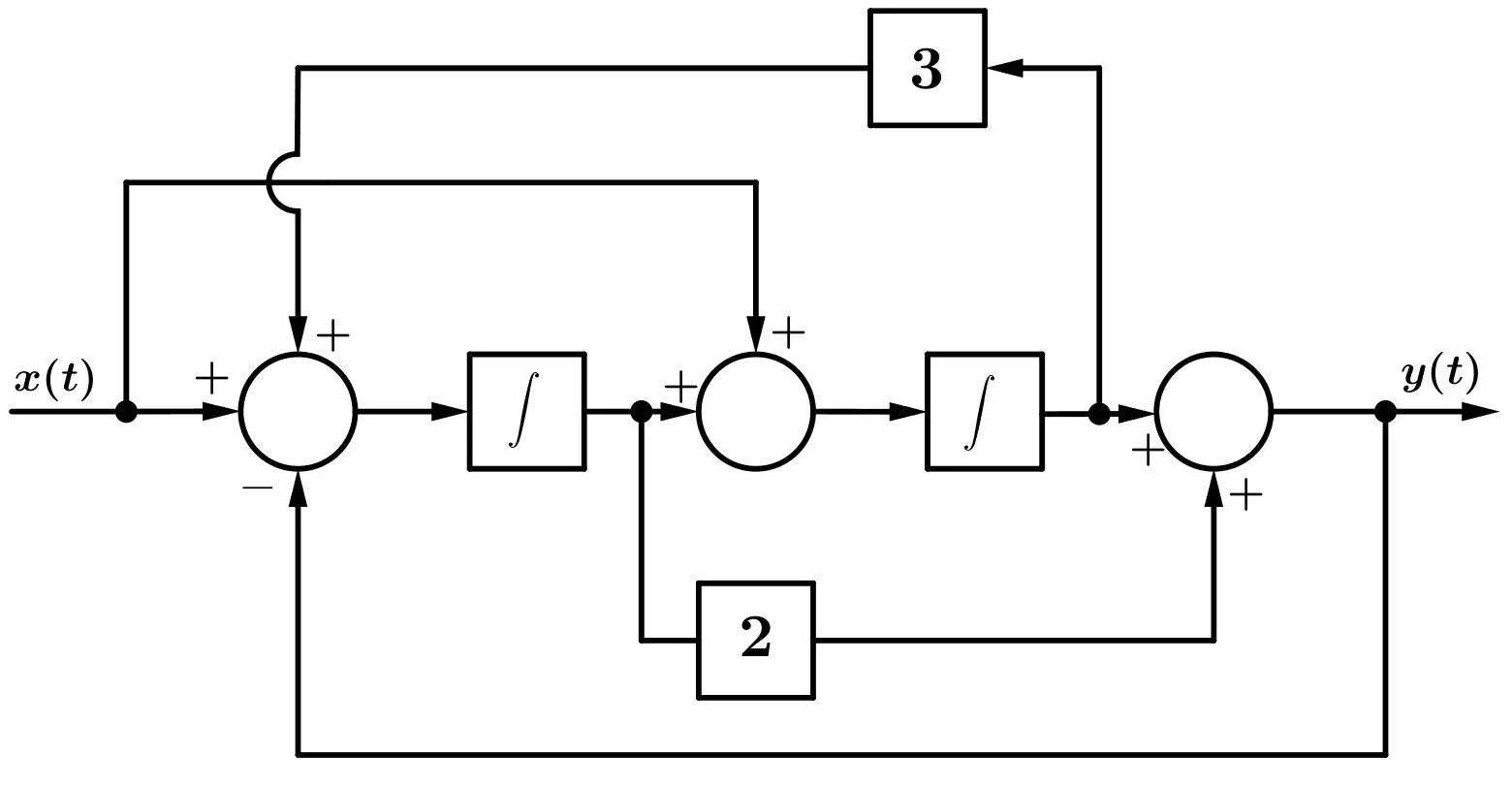 Transfer Function Of Block Diagrams Exercise 1
 Transfer Function Block Diagram Of Dc Motor Download Scientific
System Block Diagrams Noise And Disturbances Bodetechnics
Open Loop Transfer Function Block Diagram Amazing Fig 6 Block

0 Response to "Transfer Function From Block Diagram"
Post a Comment