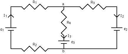
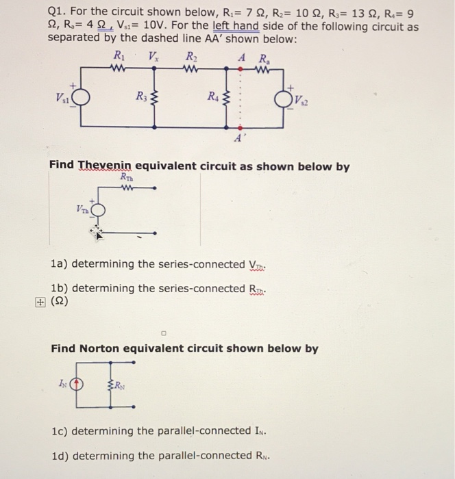
Consider The Circuit In The Diagram Below In Which R 13 ω
Consider the circuit shown in the diagram below. R total 128 132 26 ohms next find the total current using ohms law.

To find the total resistance of the circuit simply add r1 to the equivalent parallel resistance of 128 ohms to get.

Consider the circuit in the diagram below in which r 13 ω. The battery has a voltage v 120 v and the res. 0 ω r 3 6. If this was a.
0 ω r 2 13. 00 ω r 4 5. R 190 ω a find the current in the r 190 ω resistor.
A b find the potential difference between points a and b. A calculate the magnitude of the current in the r 5 resistor. Calculate the current through r4.
Yes you are definitely on the right track. Assume r1 115 ω and r2 300 ω a find the potential difference between points a and b. Right now it looks like you have calculated the circuit current current through the battery.
The total circuit resistance is then 10 ω ½r which is equivalent to εi 10 v05 a 20 ω 10 ω r2 in the circuit shown above the value of r for which the current i is 05 ampere is. I vr 12 26 462 amps. What is the equivalent resistance of the circuit shown below if r1 95 ω and r2 174 ω.
The link to the diagram can be found below consider the circuit shown in the figure below. Assume r1 20 ohms and r2 40 ohms and r3 80 ohms. 0 ω and v 24.
If the voltage source is 100 v what is the total current flowing in this circuit. Consider the circuit shown in the diagram below for r1 5 ω r2 8 ω r3 8 ω r4 8 ω and v0 80 v. Consider the circuit shown in the figure.
Consider the circuit shown in the diagram below. 00 ω r 5 18. R 1 12.
The battery has a voltage v 120 v and the resistors have the following values. By looking at the circuit you can see that all of this current must pass through r1 to return to the battery. Need help understanding how to do these problems thanks image url below a what is the equivalent resistance of the circuit shown below if r1 95 ω and r2 174 ω.
Consider the circuit shown in the figure below. Consider the circuit diagram shown here. The battery has a voltage v 120 v and the.
Seminar Assignments Assignment 1 9 With Solutions Engg 225
 Microwave Spectroscopy Of Spinful Andreev Bound States In Ballistic
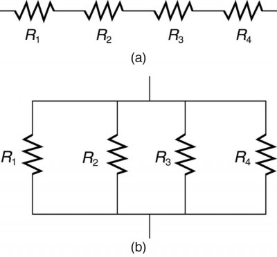
 Parallel Resistors Electric Circuits Siyavula
 Simple Series Circuits Series And Parallel Circuits Electronics
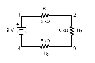
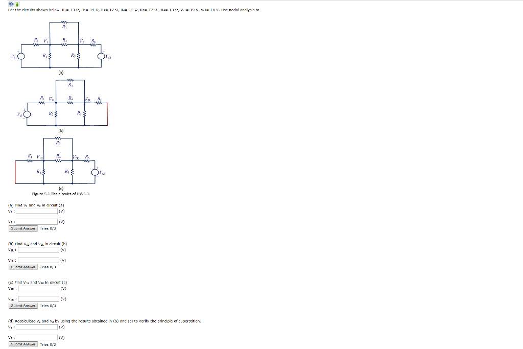 Solved For The Circuits Shown Oelow R 13 W Rjz 14 Si R
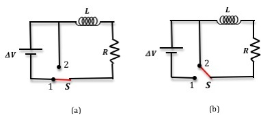 Lab 7 Lr Circuits
 Parallel Resistors Electric Circuits Siyavula
 Ohm S Law Electric Circuits Siyavula

Ph203 Chapter 23 Solutions Tactics Box 23 1 Using Kirchhoff S Loop Law
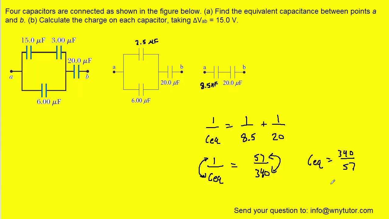 Four Capacitors Are Connected As Shown In The Figure Below Youtube
 Resonant Inductive Coupling Wikipedia
 Transformation Of Resistances Star To Delta And Delta To Star
 Kirchhoff S Current Law Kcl And Junction Rule
19 2 Series Circuits Texas Gateway
 Circuit Problems Nzmaths
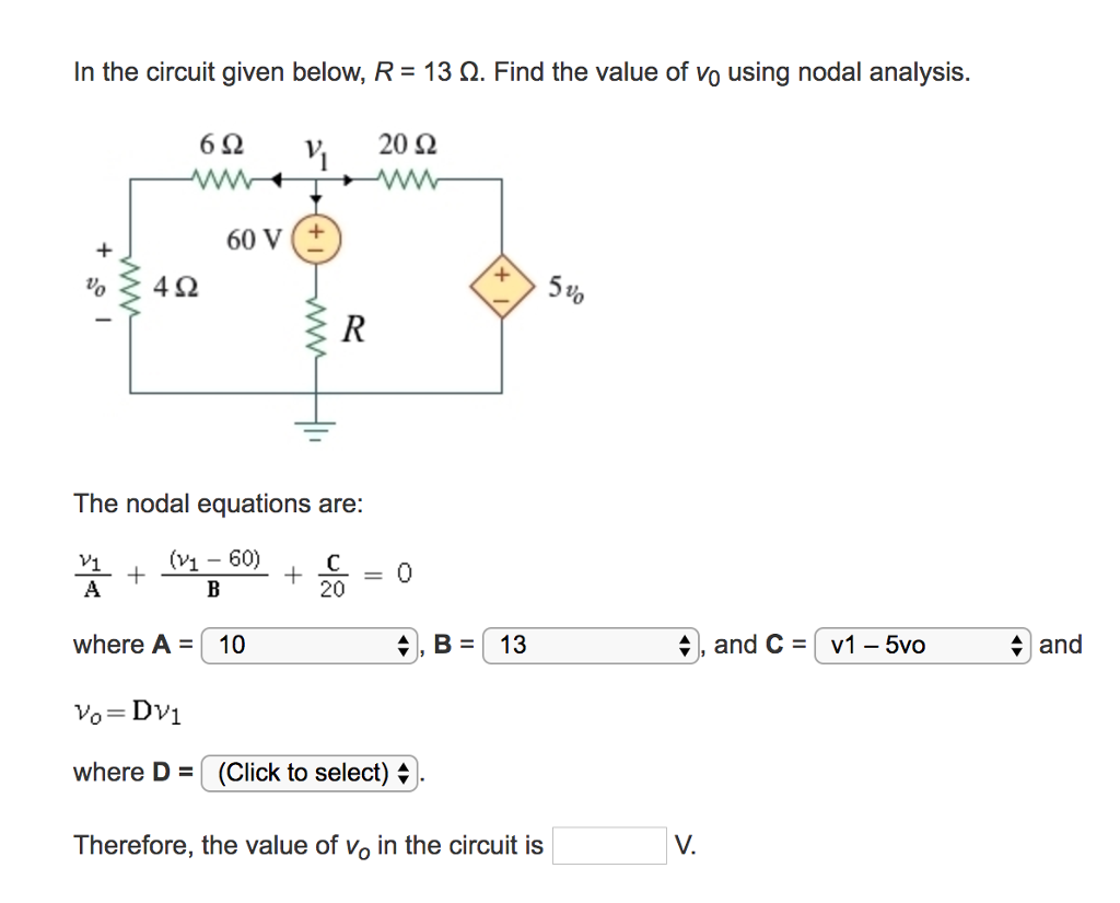 Solved In The Circuit Given Below R 13 Ohm Find The V
Physics 121 Practice Problem Solutions 08a Dc Circuits
 Solved 2 Let 18 1 5 Amp R1 200 W R2 100 W R3 50 W An
Resistive Components In Circuits
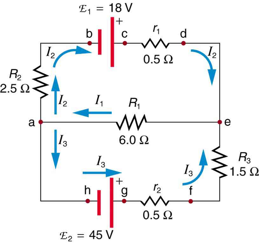 Kirchhoff S Rules Physics
Course Updates
 Ohm S Law Electric Circuits Siyavula
Ph203 Chapter 23 Solutions Tactics Box 23 1 Using Kirchhoff S Loop Law
19 2 Series Circuits Texas Gateway
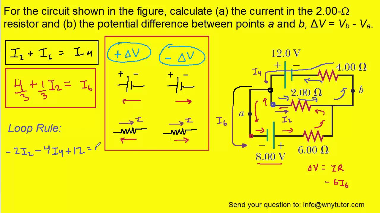 For The Circuit Shown In The Figure Calculate A The Current In
 Potential Difference And Resistor Voltage Division
Answers To Circuits
 Resistors In Series And Parallel Physics
 Circuit Terminology Article Khan Academy
Ph203 Chapter 23 Solutions Tactics Box 23 1 Using Kirchhoff S Loop Law
0 Response to "Consider The Circuit In The Diagram Below In Which R 13 ω"
Post a Comment