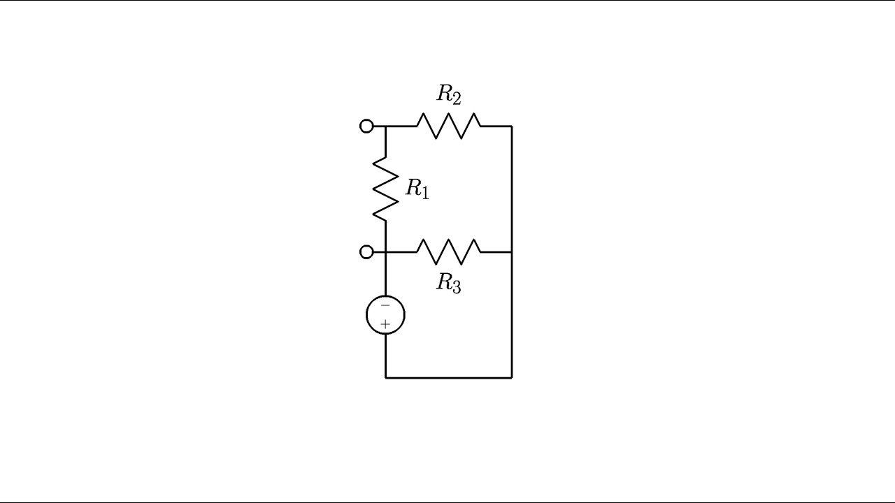
Consider The Circuit Diagram In The Figure
In the circuit shown in the figure all the lightbulbs are identical. The terminals in figure 3 divide the circuit into two parts the part to the left of the terminals and the part to the right of the terminals.
 Circuit Terminology Article Khan Academy
Which one of the figures below is the most appropriate circuit diagram for the ammeter.
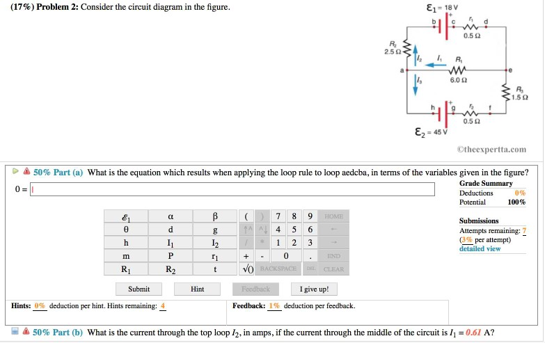
Consider the circuit diagram in the figure. B what is the current through the top loop i 2 in amps if the current through the middle of the circuit is i 1 063 a. 4 single largest rectangle. What is the magnitude of delta v.
B if the current through the top branch is i 2 0605 a what is the current through the bottom i 3 in amps. Computing some equivalent resistance of r. The light bulb in the circuit diagram of figure 1 has a resistance of eq070 omega eq.
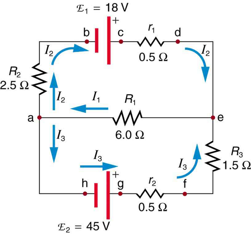
2615 consider the circuit sketched. Calculate the emfs ε1 and ε3. B find the total power dissipated if the.
The lightbulb in the circuit diagram of figure 1 has a resistance of 11 ω. Consider the potential difference between pairs of points in the figure. A what equation do you get when you apply the loop rule to the loop abcdefgha in terms of the variables in the figure.
Find the values of the voltage vc and the current ib. Consider the circuit diagram depicted in the figure. A what is the equation which results when applying the loop rule to loop aedcba in terms of the variables given in the figure.
Suppose that v1 60 v v2 25 v and is 35 a. The principles known as kirchhoffs rules in honor of the man who developed them provide a means of obtaining enough independent equations to solve for the currents flowing in an electrical circuit. A what equation do you get when you apply the loop rule abcdefgha in terms of the variables in the figure.
E1 28 v. To apply kirchhoffs rules to a direct current network and compare calculated currents with measured currents. Consider the circuit shown in figure p2129.
Consider the circuit in figure 1. Findathe current in the r 1 20 resistor andbthe potential di erence between points aand b. B if the current through the top branch is i 2 038 a what is the current through the bottom i 3 in amps.
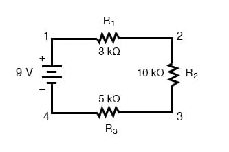
Figure 3 the circuit considered in example 2. R 3 100 v 250 v r 4 100 r 5 500 500 r 2 1 200 a b label the voltage v 250 v and the resistances clockwise from b r 1 200 r 2 500 r 3 100 r 4 100 and r 5 500. Express your answer to three significant figures and include the appropriate units.
Consider the circuit shown in figure 3. Note that two currents are shown. A find the total power dissipated in the circuit.
Consider the potential difference between pairs of points in the figure. Consider the circuit diagram depicted in the figure. Consider the circuit diagram in the figure.
 Circuit Diagram Let Us Consider The Lookup Table Function F A Bc
 Kirchhoff S Current Law Kcl And Junction Rule
 Schematic Diagram Of A Two Neuron Winner Take All Circuit Now
Physics Laboratory Manual Phyc 10190 2014 2015
 Common Collector Amplifier Basic Electronics Tutorials
 Circuit Terminology Article Khan Academy
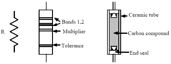
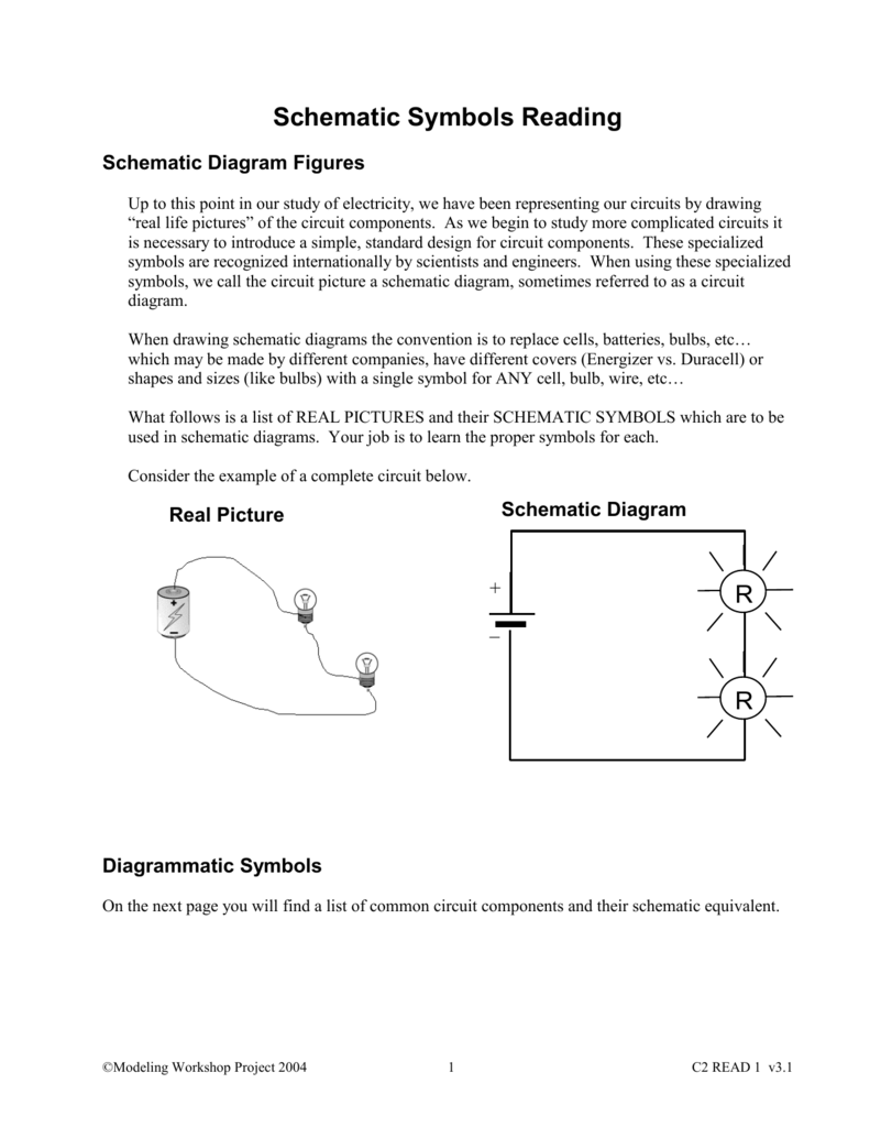 Schematic Symbols Reading
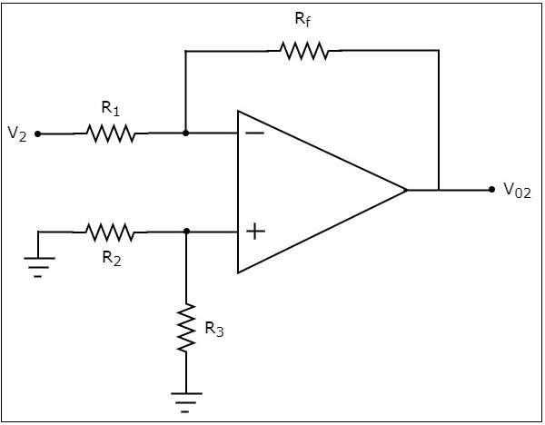
 Solved Consider The Circuit Diagram Of The Basic Invertin
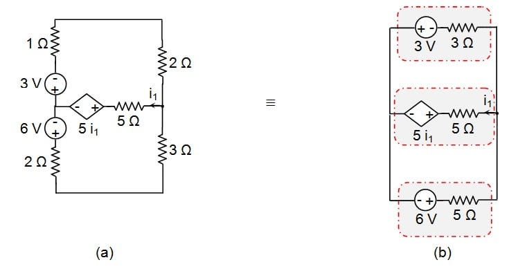 Analyzing Circuits Via Source Transformation
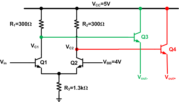 The Basics Of Emitter Coupled Logic
Examples Of Solved Problems For Chapter 3 5 6 7 And 8
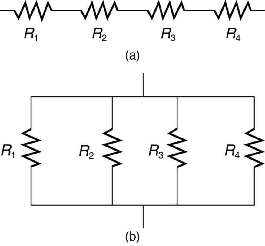
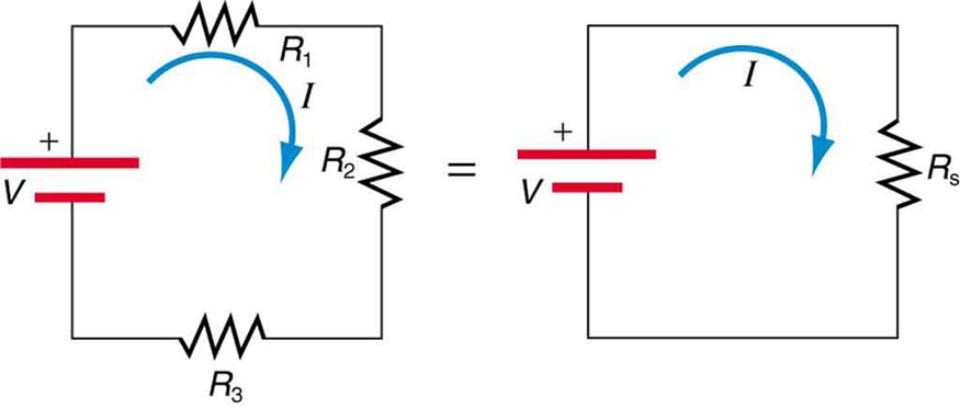 Resistors In Series And Parallel College Physics
 Skill Builder Reading Circuit Diagrams Make
 Kirchhoff S Rules Physics
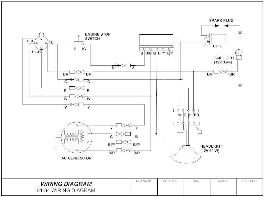
 Wiring Diagram Everything You Need To Know About Wiring Diagram
Ph203 Chapter 23 Solutions Tactics Box 23 1 Using Kirchhoff S Loop Law
 Wiring Diagram Wikipedia
 Schematic Diagram Of A Two Neuron Winner Take All Circuit Now
 Adder Circuit An Overview Sciencedirect Topics
1 Is Mass And A I Is The Change In Temperature 3 Consider The
 Resistors In Series And Parallel College Physics
 Linear Integrated Circuits Applications Quick Guide
 Ohm S Law Electric Circuits Siyavula
 Ohm S Law And Electrical Circuits
 Two Rlc Circuits Connected Through A Mutual Inductance M In Section
 Consider The Circuit Shown In The Figure Whose Input And Output Are
 Simple Series Circuits Series And Parallel Circuits Electronics
 Parallel Resistors Electric Circuits Siyavula
 Wiring Diagram Everything You Need To Know About Wiring Diagram
 Kirchhoff S Current Law Kcl And Junction Rule
 Schematic Diagram Of The Winner Take All Circuit For Analysis Of The
 Ohm S Law Electric Circuits Siyavula
0 Response to "Consider The Circuit Diagram In The Figure"
Post a Comment