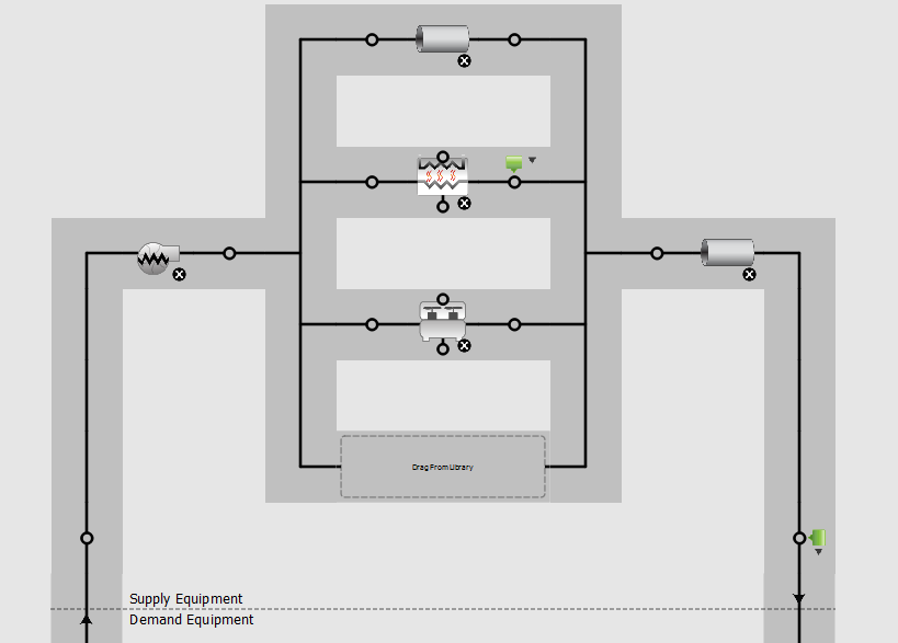
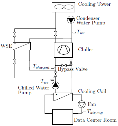
Water Side Economizer Diagram
Configuration during the epas 2006 conference on enterprise servers and data centers oracle addressed an economizer retrofit where space was a particular concern. A water economizer system shall either have a water side pressure drop of l ess that 15 ft of water or a secondary loop shall be created so that the coil or heat exchange r pressure drop is not seen by the circulating pumps when the system is in the normal cooling noneconomizer mode.
 Water Side Economizer Cooling Stulz Usa
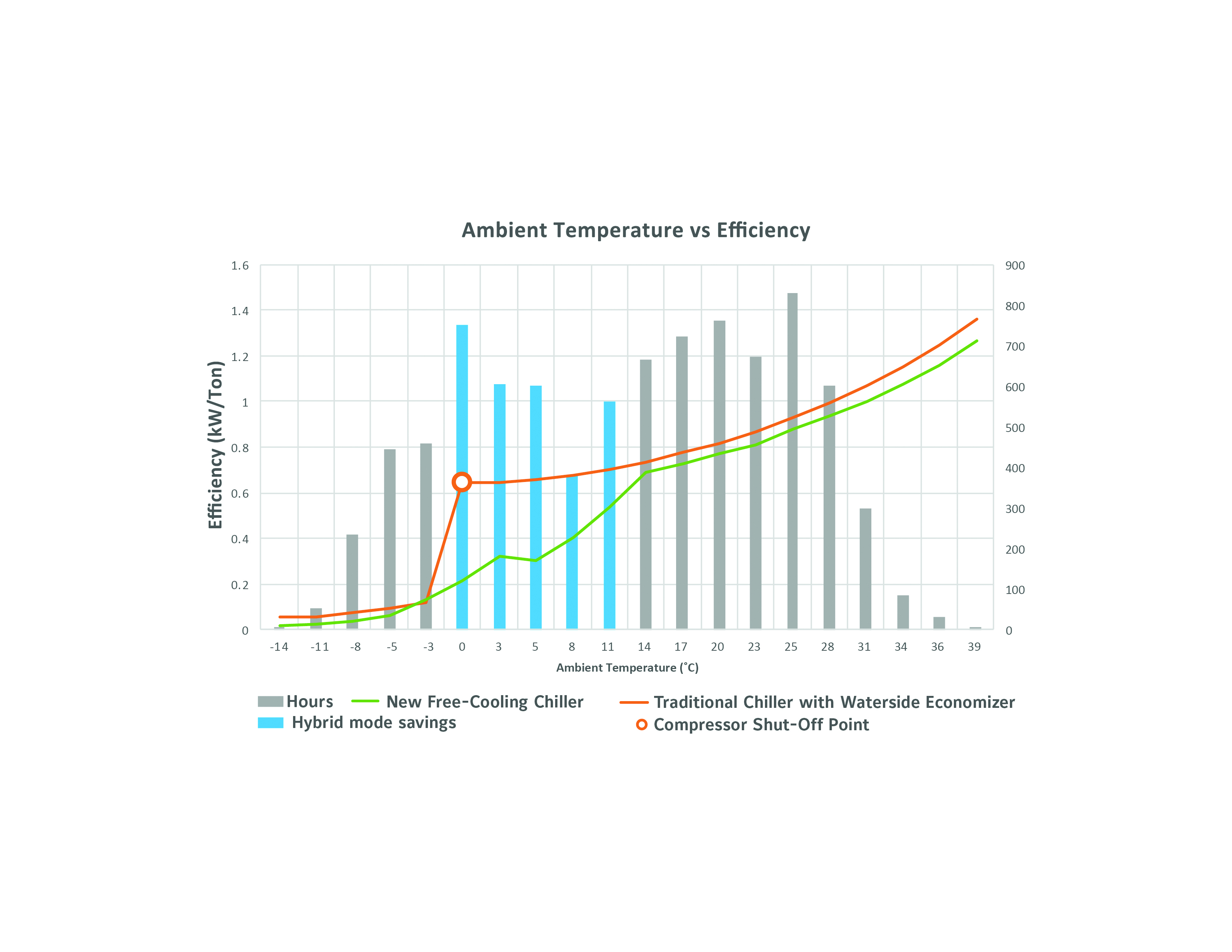
The electric savings from precooling the chilled water return chwr with a water side economizer is shown in figure 1.

Water side economizer diagram. Rather the chillers and economizers must be able to work in concert with one another when conditions permit with the economizer pre cooling the return chilled water before it enters the chillers thus alleviating some of the load. Enable the economizer if the chilled water return temperature is greater than the predicted heat exchang er leaving water temperature phxlwt plus 2f 11c. When selecting a water side economizer solution the optimal solution is dependent on several factors and preferences including available infrastructure climate region redundancy requirements ability to supportservice different equipment and available capital versus operating budget.
For data centers with water or air cooled chilled water plants a water side economizer uses the evaporative cooling capacity of a cooling tower to produce chilled water and can be used instead of the chiller during the winter months. The latter works under the same principle as the two staged booster displays with subcooling. The 2f 11c differential is needed to avoid expending a lot of cooling tower fan energy for only minimal econo mizer load reduction.
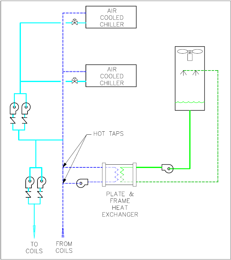
A chiller is a machine that removes heat from a liquid via a vapor compression or absorption refrigeration cycle. The economizer is installed between the chiller and the data center. Integrated waterside economizer operation waterside economizer plant components there are several components required to achieve water side economizer operation.
The benefit to this of course. Selected climate zones analyzed are shown. There are two types of economizer setups for these compressors flash and subcooling.
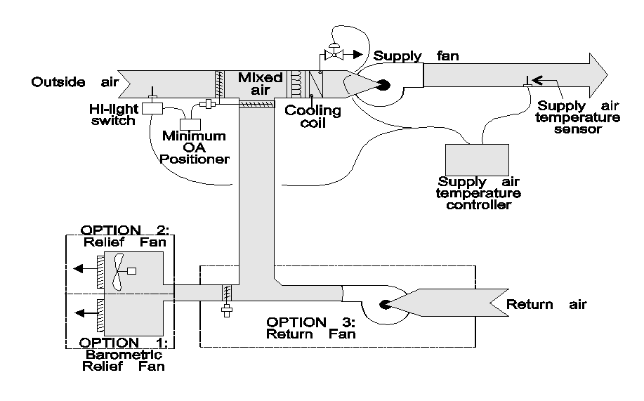
The flash economizer is different because it doesnt use a heat exchanger to produce the subcooling. The previous section described the importance of leaving chilled water temperature to a particular building load environment. When the temperature or enthalpy of the outdoor air is low cooler outdoor air is used to reduce the temperature or enthalpy of air entering the cooling coil.
The most prevalent technique is an air economizer. The additional parts new pipes valves and controls require physical space. The gross chiller savings is shown with the added energy for closed circuit cooling tower pumps and fans subtracted resulting in a net energy savings.
This can reduce or eliminate mechanical cooling for much of the year in many climates. No more parallel piping of economizers with chillers.
 Data Center Cooling Air Side And Water Side Economizers
 Chiller Schematic Showing Refrigerant Side Economizer Bypass Check
 Computerized Controls Enable Increasingly Sophisticated Algorithms

 Hvac Economizer Diagram Wiring Diagram Schema
Water Side Economizer For Non Fan Cooling Systems
Waterside Economizing In Data Centers Design And Control Considerations
Brian Meneghan

Docketed
 Water Side Economizer Heatexchanger Fluidtofluid Override Will Not
Water Side Economizer For Non Fan Cooling Systems
How To Design Control Waterside Economizers
Analysis Of Air Side Economizers In Terms Of Cooling Energy
 10 4 Computer Rooms
Waterside Economizer For Right Hand Vertical Csv300b Style B Water
Waterside Economizer For Right Hand Vertical Csv180b Style B Water
How To Design Control Waterside Economizers
How To Model A Waterside Economizer Application
 Schematic Of Airside Economizer With Airflow Path 7 Download
Waterside Economizer For Right Hand Vertical Csv180b Style B Water
 Schematic Of The Ibal Hydronic System Hx3 Is The Water Side
How To Model A Waterside Economizer Application
Waterside Economizing In Data Centers Design And Control Considerations
 Nr 4 5 Hvac System Control Requirements
Commercial Energy Systems Free Cooling
An Innovative Approach To Economizers In Datacenters Shrenik Ajmera
Economizers In Chiller Systems
 Buildings Examples Chillerplant
Water Side Economizer For Non Fan Cooling Systems
 Dedicated Waterside Economizers Types

 Energy Saving Potential Of Various Air Side Economizers In A Modular
0 Response to "Water Side Economizer Diagram"
Post a Comment