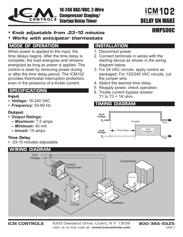
Delay On Break Timer Wiring Diagram
A wiring diagram is a simplified traditional pictorial depiction of an electric circuit. In addition true off delay timers provide this functionality keeping contacts closed after input voltage is lost.
Mzl 26 12v Ignition Sensing Delay Timer Acdc Industries
13039 visit us on the web at.

Delay on break timer wiring diagram. I need to replace a broken watsco timer in my outside unit and found an ams24a300 but am not sure which terminal is which as they are only labeled 1 2 and 4. Cube relay 10 30 amps timing mode. Collection of dayton off delay timer wiring diagram.
View is from the flat side with the catalog numbers. It is perfect to use when either a magnetic lock or electric strike is installed on an automatic door. Kh1 series fixed time on delay external connection diagram.
They have capacitors to keep contacts closed even if the timer loses power. Time delay is factory preset to one specific time 5 seconds for example. Delay on break 6333 daedalus drive cicero ny.
Module load at pin 2 is a relay coil. Variety of delay on break timer wiring diagram. The external initiate switch opens the time delay is started.
Tgm 072816 pelco component technologies 855 227 3526 specificationsfeatures. A wiring diagram is a simplified standard pictorial depiction of an electric circuit. Delay on break category.
Mode of operation upon application power the load is energized. Application wiring for fixed dc time delay module figure 3. It shows the components of the circuit as streamlined shapes and also the power and signal connections in between the tools.
Where to find the wiring diagram for icm ams series delay on break timers. Delay delay on break timers anti short cycle on delay on break helps to protect air conditioning refrigeration and heat pump equipment from damage which may be caused by the rapid short cycling of compressors. Removing voltage prior to time out resets the timing and opens the contacts.
It reveals the parts of the circuit as streamlined shapes and the power as well as signal links between the devices. Timer with relay series. Delay on break timer with 03 10 minute adjustable time delay universal 18 240 vac details.
There are special contact symbols for the on delay and off delay timers. At the end of the time delay the load is de energized and the timer is ready for another cycle. Icm controls icm203 icm203 delay on break timer 03 10 minute knob adjust.
The delay on break timer will release the lock and then the delay on make timer will enable the door to open and be held open for a set period of time. 10mc25 is a delay on make delay on break time delay. Compressor lockoutanti short cycle timer helps to protect compressors from damage caused by rapid short cycling simple 2 wire hookup adjustable timing universal voltage.
1 Minute 5 Minute 10 Minute And 15 Minute Timer Circuit Diagram
 Delay Relays Delay On Make Vs Delay On Break Functional Devices
 Delay On Break Timer Time Delay Relays Littelfuse
Wiring Diagram Timer Lampu Wiring Diagram And Schematic
 Eaton C25bnb230a Wiring Diagram Lovely Wiring Diagram For Contactor
 Delay Relays Delay On Make Vs Delay On Break Functional Devices
 Delay Timers And The Air Conditioner Condenser Hvac Control
 On Delay Timer Wiring Diagram Wiring Diagram Schematics
Mzl 52 12v Voltage Sensing Delay Timer Acdc Industries
Cube Relay Delayed Interval Off On Timers Tgcl Timers From Airotronics
 Time Delay On Break For Compressor Youtube
Wrg 4669 Time Delay Wiring Diagram
 Wrg 4669 Time Delay Wiring Diagram
 Mars Time Delay Relay Wiring Diagram Wiring Diagram Schematics
 Understanding Time Delay Relay Functions
 On Delay Timer Wiring Diagram Wiring Diagram Data
Mzl Fd 12v Ignition Sensing Delay Timer Acdc Industries
Simple Time Delay Circuit Diagram Using 555 Timer
Delay Timer For Motor Or Pump 120volt To 240volt
0 Response to "Delay On Break Timer Wiring Diagram"
Post a Comment