High Resistance Grounding System Diagram
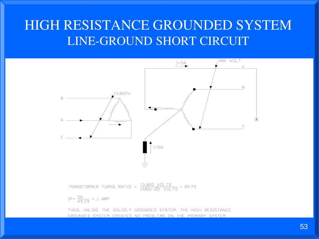
The eaton power systems experience center psec discusses high resistance grounding hrg and how helps you continue to operate with temporary or permanent ground faults. A high resistance grounded system limits the ground fault current to a value only slightly higher than an ungrounded system.
 Commercial Generator Grounding Methods Low High Impedance
In case of mv system 33kv onwards to 33kv voltage between phase and earth is high.
High resistance grounding system diagram. High resistance grounding ieee standard 142 1991 defnes high resistance grounded system as follows. High resistance grounding of the neutral limits the ground fault current to a very low level typically from 1 to10 amps and this is achieved by connecting a current limiting resistor between the neutral of the transformer secondary and the earth ground and is used on low voltage systems of 600 volts or less under 3000 amp. High resistance grounding eatons high resistance grounding solutions allow for continuous operation and increased safety during fault conditions.
53 the high resistance neutral grounding equipment will contain the following equipment on the front of the unit as standard. High resistance grounding hrg systems limit the fault current when one phase of the system shorts or arcs to ground but at lower levels than low resistance systems. Most utility systems which supply service for commercial and industrial systems are solidly grounded.
It is a simple and economical upgrade to any ungrounded system. The advantages of high resistance grounded systems are easier. This level of current is commonly thought to be a 10 a or less.
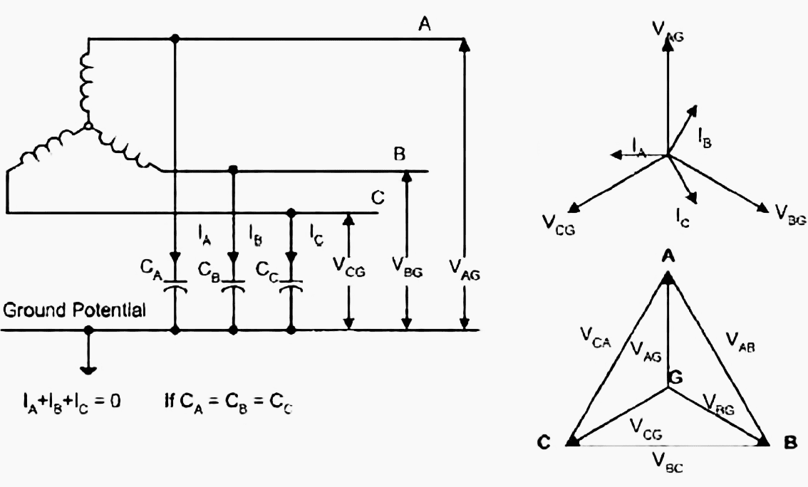
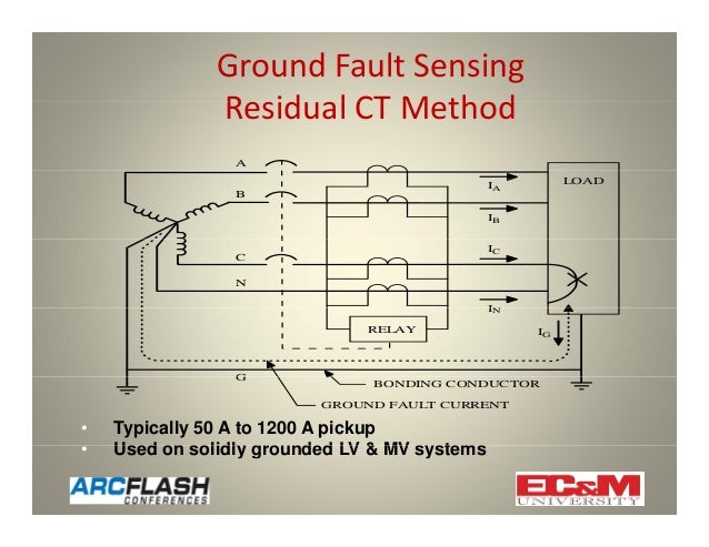
System grounding is the ratio of the available ground fault current to the available three phase fault current. A grounded system with a purposely inserted resistance that limits ground fault current can flow for an extended period without exacerbating damage. Provides ground fault detection and control of transient overvoltages during a single phase to ground fault on an ungrounded system thus minimizing the possibility of insulation failure in motors transformers power cables and electronic equipment.
Basic high resistance grounding is a simple resistor added to an ungrounded system that limits the fault current and controls the transient over voltages. Hence resistance is connected between neutral to ground connection. Figure 4 resistance grounded system.
Also capacitive charging current is not large enough to compensate the same so earth fault current is likely to be excessive. For effectively grounded systems this ratio is usually at least 60 2. The five pole disconnect switch three phases neutral to grounding resistor and neutral to sensing resistor will be equipped with properly sized fuses class cc.
In the event that a ground fault condition exists the hrg typically limits the current to 5 10a though most resistor manufacturers label any resistor that limits the current to 25a or less as high resistance. These values are small enough that it is acceptable to not trip safety devices and let faults remain on the system.
 Electrical Safety Mitigate Arc Flash Risk High Resistance
 Ground Fault Protection In Variable Frequency Drives Ee Publishers

Francis K Fox Howard J Grotts And Clyde H Tipton Ieee
 Earthing System Wikipedia
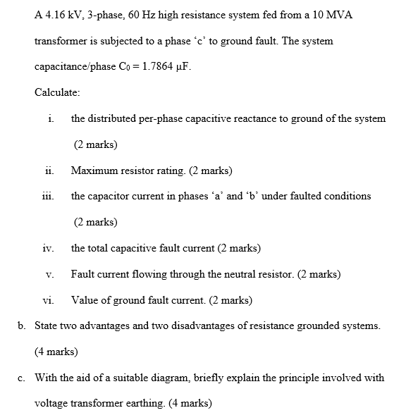 Solved A 4 16 Kv 3 Phase 60 Hz High Resistance System F
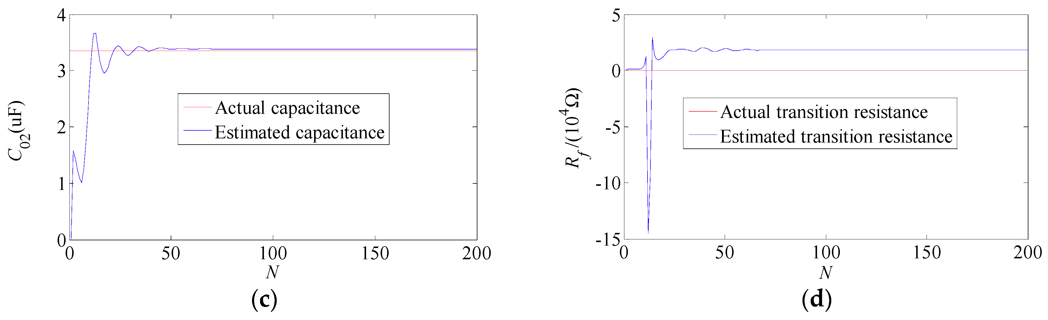 Energies Free Full Text Identifying Faulty Feeder For Single
Low Voltage High Resistance Grounding System Basics C Hrg Technical
C 100ea Ngr Application Guide Indd
 Earthing Of Electrical Transmission Tower Electrical4u
 Marine Grounding Systems West Marine
 Characteristics Of A Good Earthing System Ets Cable Components
![]() Grounding Transformer Wikipedia
Grounding Transformer Wikipedia
 Figure 10 From Selective High Resistance Grounding System For A
 Ground Fault Protection On Ungrounded And High Resistance Grounded
 Grounding Lightning Protection High Resistance Grounding
 High Resistance Ground Wiring Diagram Wiring Diagram
 Presented By John S Levine P E Levine Lectronics And Lectric Inc
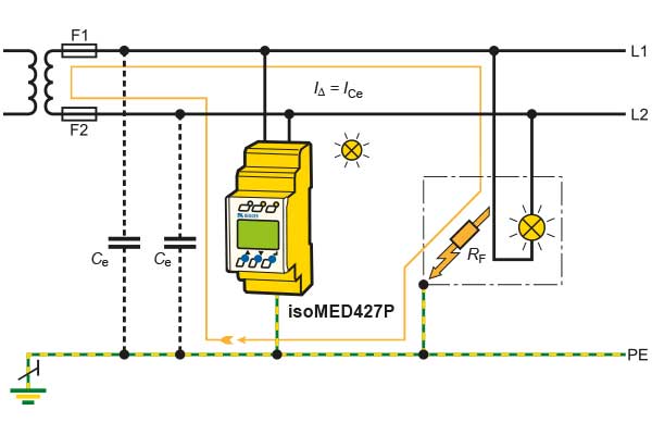
It System Unearthed Systems For Maximum Availability Bender
 High Resistance Ground Wiring Diagram Wiring Diagram
 Using High Resistance Grounding To Mitigate Arc Flash Hazards
 Lightning Surge Protection And Earthing Of Electrical Electronic
 The Principles Protective Multiple Earthing Pme
 High Resistance Grounding System Ground Fault Detection Scheme

0 Response to "High Resistance Grounding System Diagram"
Post a Comment