Phase Locked Loop Block Diagram
The main blocks of the pll are the phase frequency detector pfd charge pump loop filter voltage controlled oscillator vco and. It is a very useful device for synchronous communication.

Phase locked loop pll is one of the vital blocks in linear systems.

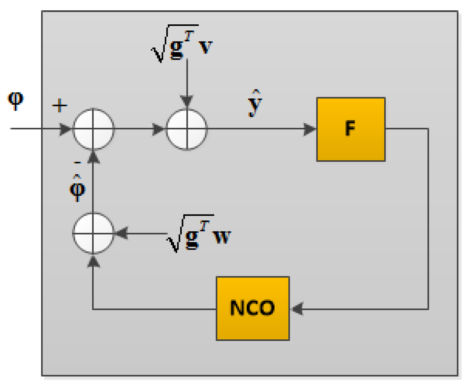
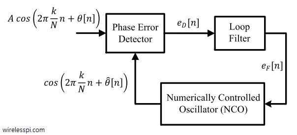
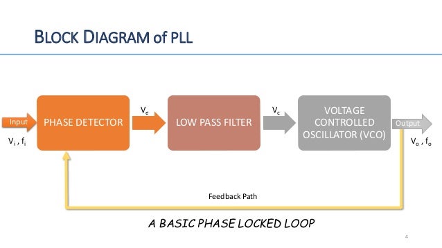
Phase locked loop block diagram. Figure 1 shows a simplified block diagram of the major components in a pll. The output of a phase detector is applied as an input of active low pass. It may also have a divider in the feedback path or in the reference path or both in order to make the plls output signal frequency a rational multiple of the reference frequency.
Phase locked loops pll introduction to pll. What is phase locked loop. A phase locked loop pll is a closed loop frequency control system based on the phase difference between the input clock signal and the feedback clock signal of a controlled oscillator.
The figure shows the block diagram of the phase locked loop system in fm transmitter that consists of different blocks such as a crystal oscillator phase detector loop filter voltage controlled oscillator vco and frequency divider. A non integer multiple of the reference frequency can also be. The phase locked loop or pll is an electronic circuit with a voltage controlled oscillator whose output frequency is continuously adjusted according to the input signals frequency.
Basic diagram of phase locked loop block diagram and working principle of pll. The phase locked loop consists of a phase detector a voltage control oscillator and in between them a low pass filter is fixed. A phase locked loop is used for tracking phase and frequency of the input signal.
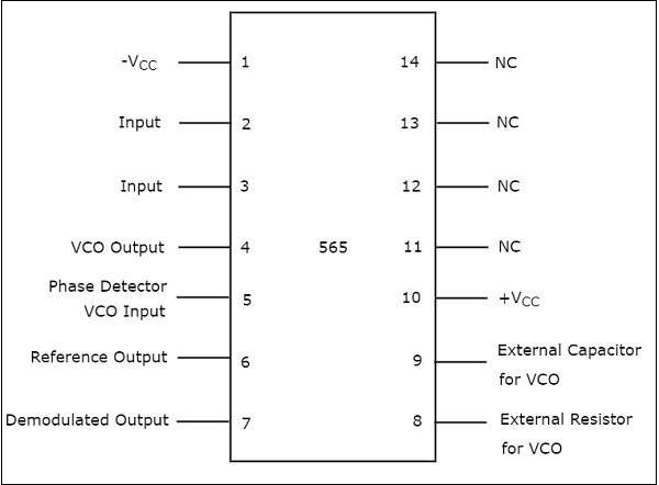
In view of its usefulness the phase locked loop or pll is found in many wireless radio and general electronic items from mobile phones to broadcast radios televisions to wi fi routers walkie talkie radios to professional communications systems and vey much more. This chapter discusses about the block diagram of pll and ic 565 in detail. The input signal vi with an input frequency fi is conceded by a phase detector.
It is the most important part of the phase locked loop system. Phase locked loop block diagram. A digital phase locked loop uses a digital phase detector.
The concept of phase locked loops pll first emerged in the early 1930âsbut the technology was not developed as it now the cost factor for developing this technology was very high. It is useful in communication systems such as radars satellites fms etc. The phase locked loop or pll is a particularly useful circuit block that is widely used in radio frequency or wireless applications.
 Linear Integrated Circuits Applications Phase Locked Loop Ic
File All Degital Pll Block Diagram 2 Png Wikimedia Commons
Basics Of Pll I Operation I Block Diagram Eeeguide Com
Reference Clock Phase Lock Loop Ni High Speed Digitizers Ni Scope
 Sensors Free Full Text Design And Implementation Of An Rtk Based
 Phase Locked Loop Pll In A Software Defined Radio Sdr Wireless Pi
 Electrical And Electronic Engineering Phase Locked Loop Pll
 Phase Lock Loop Ee174 Sjsu Tan Nguyen Ppt Video Online Download
 Linear Integrated Circuits Applications Phase Locked Loop Ic
 Principle Block Diagram Of Phase Locked Loop Download Scientific
Simulating Phase Locked Loops With Matlab
 Block Diagram Electronic Circuit Analog To Digital Converter Circuit
 Phase Locked Loop Tutorial Block Diagrams Electronics Circuit
Phase Locked Loop Project Overview For Analog Integrated Circuits
 Charge Pump Phase Locked Loop A Tutorial Part I Ee Times
 Phase Locked Loops For High Frequency Receivers And Transmitters
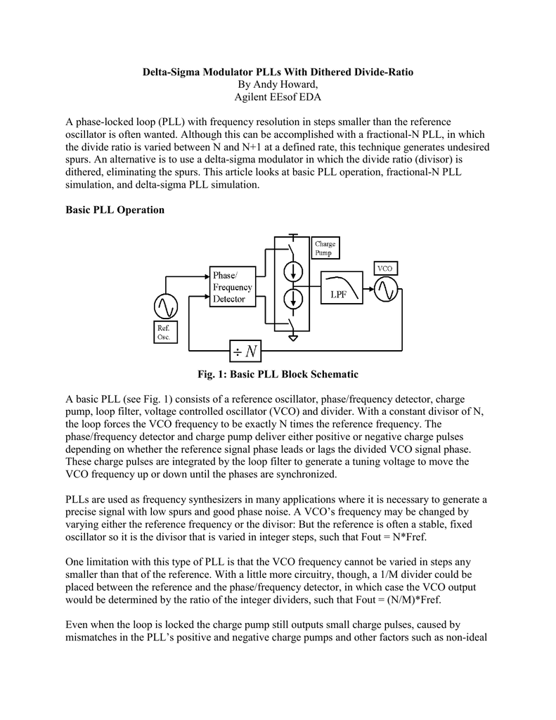 Figure 1 Shows A Basic Phase Locked Loop Block Diagram
The Following Has Been Gathered From Operating Principle Of Phase
The Operation Of The Phase Locked Loop A Phase Locked Loop
 Solved Chapter 6 Problem 23qp Solution Modern Electronic
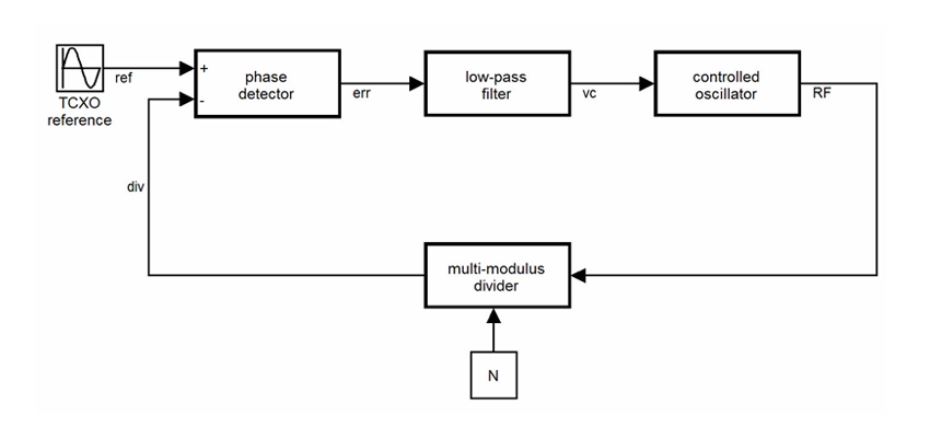 Modeling And Simulating An All Digital Phase Locked Loop Matlab
 Figure 1 From A 400mhz 2 4ghz Radiation Tolerant Self Biased Phase
Phase Locked Loops National Instruments
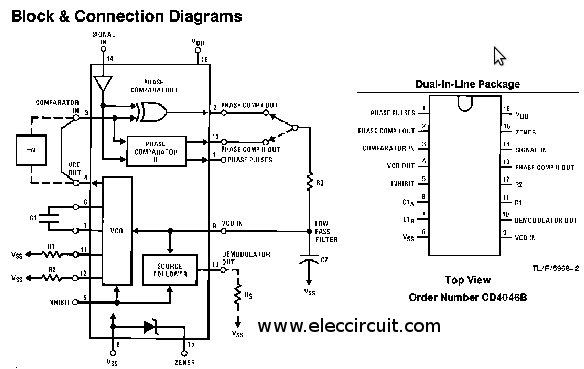 Ic 4046 Datasheet Phase Locked Loop


0 Response to "Phase Locked Loop Block Diagram"
Post a Comment