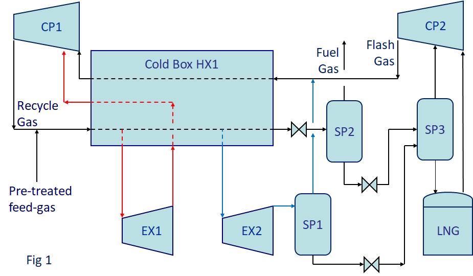
Lng Process Flow Diagram
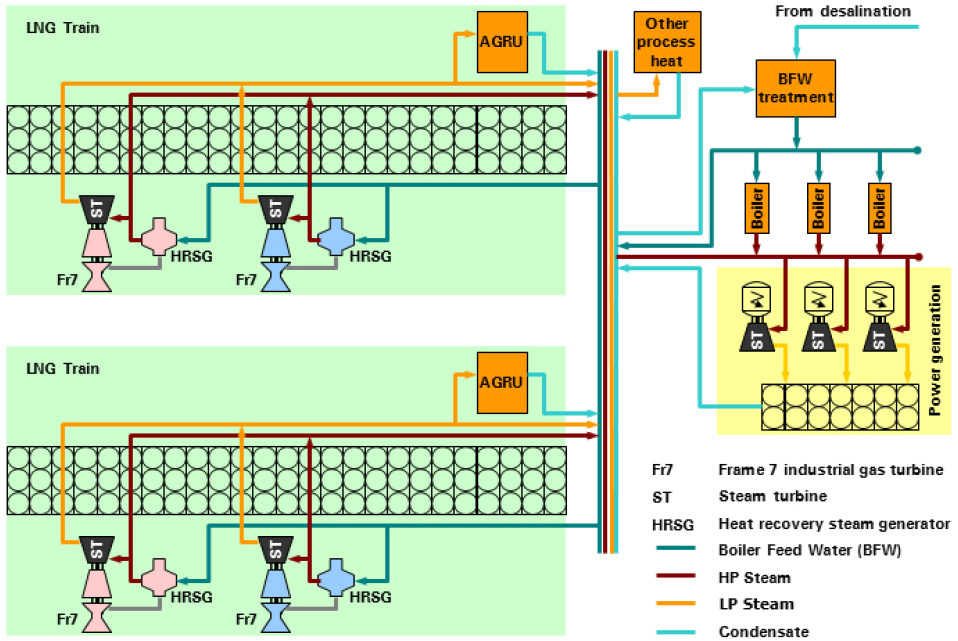
35 mw of shaft power per mta for efficient liquefaction processes where the magic happens gas in large amount of energy input driver not shown compressor. Check temperature of streams.
A Fresh Look At Lng Process Efficiency
Brazed aluminum heat exchangers charts heat exchangers and cold boxes are at the heart of low temperature natural gas air separation and petrochemical processes worldwide.

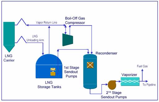
Lng process flow diagram. Slug catcher inlet facilities metering co2. Hammerfest lng plant block flow diagram. The major equipment components of an lng import and regasification terminal are.
Lng is natural gas that has been cooled and condensed to a liquid at atmospheric pressure lng has a temperature of about 162ºc lng contains about 85 95 methane lng is colorless odorless non corrosive and non toxic evaporated lng can displace oxygen and cause human suffocation. This makes lng cost efficient in marine transport over long distances. Lng storage tanks vaporization areas process areas transfer areas 49 cfr 193 lng gabriel castaneda pe.
The overall process is often quite similar. All cells in lng hx must have equal area. Optimization refrigerant composition.
Restriction needed second law of thermodynamics. Natural gas processing begins at the well head. Removal de hydration mercury removal natural gas liquefaction lpg storage condensate storage meg recovery condensate treatment co2 drying and recompression nitrogen removal fractionation refrigerant make up fuel gas system c1 c2 c3 refrig.
Restriction needed heat transfer area. Unloading arms cryogenic pipelines storage tanks low pressure pumps boil off gas bog compressors and re. Lng j t expander bypass valve lng lng flash tank lng lng lng liquefied methane gas to sub cooler j t expander bypass valve compressor anti surge valve main cryogenic heat exchanger on site ccgt power plant provides electric power for compressor drives and steam for heating processes lng liquefaction process flow diagram.
Reduction of the potential for a catastrophic spill of lng sets design spill requirements for each specific major area. A typical lng import terminal process flow diagram is shown in figure 5. What is lng.
After making simple simulations mimic real process variables were transferred to real process simulation. The composition of the raw natural gas extracted from producing wells depends on the type depth and location of the underground. Process flow diagram q high temperature ambient q low temperature sub ambient condenser suction drum compressor heat exchanger j t valve accumulatorlng out rough rule of thumb.
Lng achieves a higher reduction in volume than compressed natural gas cng so that the volumetric energy density of lng is 24 times greater than that of cng at 250 bar or 60 percent that of diesel fuel. Lng equipment systems chart is the worlds leading single source lng equipment and solutions provider across the complete value chain liquefaction distribution storage and end use. Natural gas processing is a done with process designed to clean raw natural gas by separating impurities and various non methane hydrocarbons and fluids to produce what is known as pipeline quality dry natural gas.

 Liquefied Natural Gas Lng

 Lng Plant Flow Chart Youtube
Title Arial Bold 30 Point
Swedegas Tender
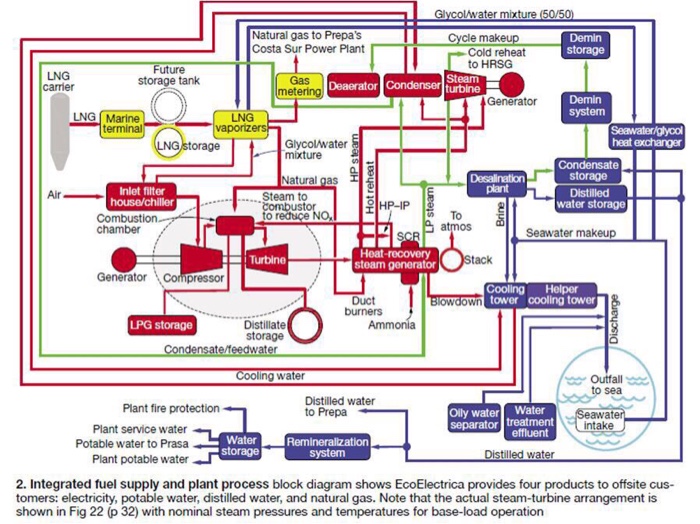
04 02 Integrated Fm
Liquefied Natural Gas And Floating Lng
Lng Plant Overview
Natural Gas Liquefaction Simplified Lng Plant Block Diagram
Giignl Has Developed Following Fact Sheet To Provide Summary
Natural Gas Liquefaction Simplified Lng Plant Block Diagram
 Process Flow Diagram Pdf Wiring Diagram Schematics
 How Does Lng Terminal Works
Lng Bunkering
 Process Flow Of A Typical Lng Receiving And Regasification Terminal
 Process Flow Diagram Pdf Data Wiring Diagram

 Lng Tank Construction Using Insulating Perlite Concrete Blocks The
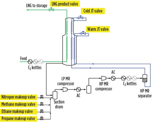
 Figure 2 From Design Optimization Of Single Mixed Refrigerant Lng
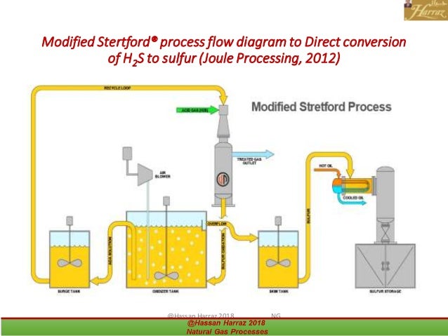 Lecture 9 Natural Gas Processes
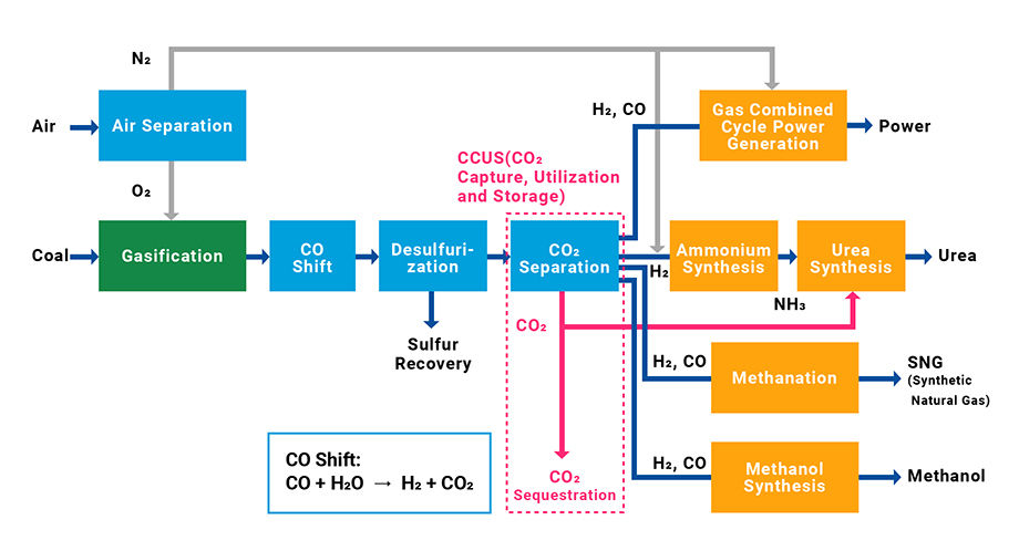 Clean Coal Technology Related To Coal Gasification Chiyoda Corporation
 Coreflux Cold Reflux Technology Toyo Engineering Corporation
 Process Flow Diagram For The Advanced Three Stage Rankine Cycle
 Engineering Process Flow Diagram Wiring Diagram
Giignl Has Developed Following Fact Sheet To Provide Summary


0 Response to "Lng Process Flow Diagram"
Post a Comment