Electric Motor Brake Wiring Diagram
Three phase wiring diagrams always use wiring diagram supplied on motor nameplate. Special light and wiring systems need to be installed on your tow vehicle before you can tow any trailer.
 Electric Bike Controller Wiring Diagram In Addition Motor E Sparky
Mounting the motor casing onto the brake and fan completes.

Electric motor brake wiring diagram. Sew eurodrive motors wiring diagram collections of electric motor brake weg electric motors wiring diagram free. Collection of electric motor brake wiring diagram. It shows the parts of the circuit as simplified forms and the power and signal connections between the tools.
Basically an e brake means when you hit one of the brake levers the motor power is momentarily cut offthis makes it hard to accidentally hit your brakes and the throttle at the same timethis requires of course two more sets of wires going from your controller. Sew motor wiring diagram motor repalcement parts and diagram wire. For rapid brake reaction time incorporate the contact as shown on the brake diagram lo.
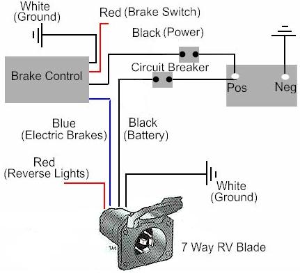
Tail light converters brake control wiring vehicles towed behind a motorhome wiring diagram for common plugs breakaway switches. Three phase motor power control wiring diagrams 3 phase motor power control wiring diagrams three phase motor connection schematic power and control. Sew motor wiring diagram motor repalcement parts and diagram wire.
Electric heating is always. Connect the brake supply cable inserted into the motor terminal box according to the diagram on the inside of the box cover while connecting the brake with the motor maintain all the necessary safety measures and precautions pertaining to the handling of electrical equipment 9. Remove and lockout all power from the electric motor and brake before any work is completed on the brake.
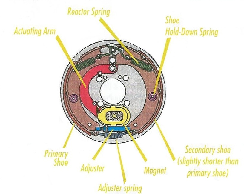
These brakes are designed to stop or hold when power is removed from the brake de energized and allow motor motion when the brake is powered energized. Always use wiring diagram supplied on motor nameplate. Sew motor wiring diagram motor repalcement parts and diagram wire.
Whoever invented ebike safety etiquette has decided that an e brake is critical safety equipment on an electric bike. On this page are for normal brake reaction time. Electrically released brakes are commonly used with motors or brake motors to rapidly slow down a system or prevent a system from moving altogether.
The user is responsible for conforming to all national and local electrical and safety codes. Trailer wiring and brake control wiring. For low ambient temperatures the bmh brake rectifier with a heating current is available for heating the brake while the motor is at rest.
Wiring practices proper grounding disconnects and over current protection. Brake voltage supplied from the motor. Motor brakes installation maintenance retain for future use.
A wiring diagram is a streamlined standard photographic representation of an electric circuit.
 48 60v Brushless Dc Motor Controller E Bike Conteollers Electric
 Sew Eurodrive 6 Lead Motor Wiring Diagram Siteandsites Co
Controllers For Three Phase Motors
Bodine Electric Motor Wiring Diagram Elegant Bodine Dc Gear Drive
Top Dual Capacitor Wiring Diagram Ac Dual Capacitor Wiring Diagram
 How To Install A Electric Trailer Brake Controller On A Tow Vehicle
 Hp Marathon Electric Motors Wiring Diagrams Free Download Wiring
 3 Phase Electric Motor Wiring Diagram Data Schema Exp
 Siemens Motor Wiring Diagram Everything Wiring Diagram
 Induction Motor Braking Regenerative Plugging Dynamic Braking Of
 Electric Bike Controller Wiring Diagram In Addition Electric Motor
Brake Motor Wiring Diagram Wiring Diagram
 Wiring Diagram Electrical Wires Cable Schematic Philips Emergency
Electric Motor Wiring Diagram Wiring Diagram Data Today
Lincoln Ac Motor Wiring Diagram Wiring Diagram G9
Electric Trailer Brake Controller Wiring Diagram New U Haul Brake
 Collection Limit Switch Wiring Diagram Relay Switches To Control
 High Voltage 6 Lead Motor Wiring Diagram Wiring Library
 Leeson Motor Drum Switch Wiring Diagram For A Schematic Three Way
 Baldor Brake Wiring Diagram Wiring Diagram
 Motor Control Wiring Diagram Access Basic Simple Infrared Remote
 Simulate An Ac Motor Drive Matlab Simulink
Rascal Scooter Wiring Diagram 24 Related Articles Rascal 245 Scooter
 Contactor Wiring Diagram Brake Wiring Diagram
 Baldor Brake Wiring Diagram Wiring Diagram
Electric Motor Diagram Wiring Wiring Diagram Schema Blog
Genuine Electric Motor Brake Wiring Diagram Ac Motor Wiring Diagram
 Electric Motor Wiring Diagram Wiring Diagrams The
 Pole Switch Wiring Diagram Motor Repalcement Parts And Diagram
P3 Wiring Diagram Bestsurvivalknifereviewss Com
 Motor Controller 36v 48v 1000w Electric High Brushless Speed
 Service And Maintenance Sew Eurodrive Driving The World Pdf

0 Response to "Electric Motor Brake Wiring Diagram"
Post a Comment