Radiant Heat Mixing Valve Diagram
Taco mixing valves 5000 series taco thermostatic mixing valve 2 way i series. This creates a circulating loop of hot water between the heater.
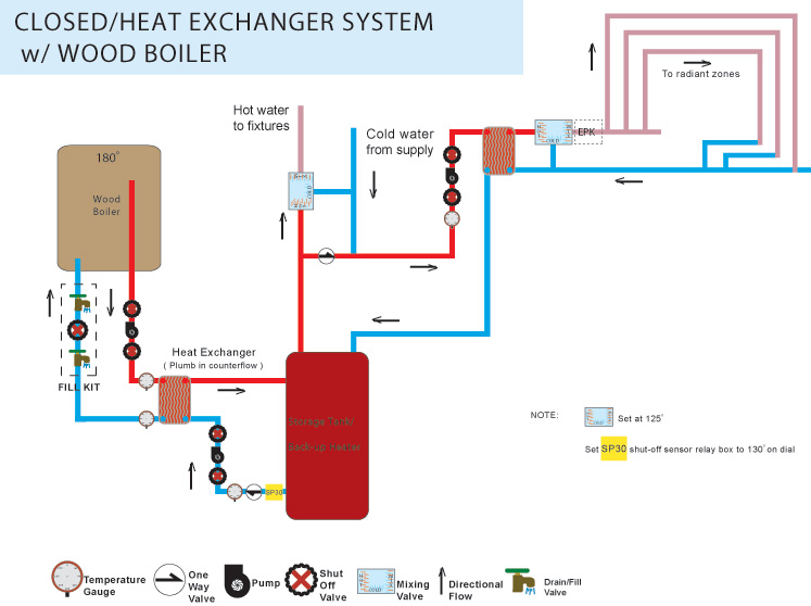
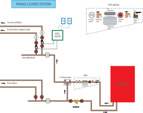
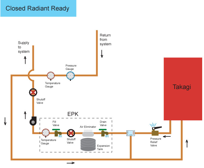
 Radiant Heat Open System Diagram The Closed System Diy Radiant Floor
Roth radiant heating installation handbook page 4 mounting instructions 65 76 boiler with variable speed injection pump 73 power requirements 65 78 boiler with 2 temperature variable speed injection pumps 74 adjustments 65 79 boiler with dhw air handler and 4 way mixing valve.
Radiant heat mixing valve diagram. The much cooler radiant floor zones receive tempered water from the mix port of the mixing valve. The baseboard or cast iron radiator zones for example receive super hot water straight from the heat source. Mixed supply setpoint can be configured to reset from the outdoor air temperature.
Tips for properly installing these mixing valves in radiant heating systems. Its available from several manufacturers with either an internal thermostatic element or an external actuator. In a radiant heating application a properly sized pump on the primary loop triggers the on demand heater whenever any zone calls for heat.
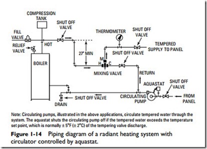
When such controls sense low boiler return conditions they partially close the mixing valve or slow the speed of the injection pump to prevent the distribution system from stripping heat out of the water faster than the boiler can produce it. Most modern electronic mixing controls include boiler return protection as part of their programming. Mixing valves and controls for in floor radiant heating a solid control apparatus is the cornerstone of a well designed in floor radiant heating system.
One of the best known temperature control devices in hydronic radiant heating systems is the three way thermostatic mixing valve. Taco mixing valve 3 way indoor outdoor reset mixing valves. I think i need to run a separate circulator for each manifold with a 3 way mixing valve for both manifolds to regulate.
Primarysecondary plumbing has been used for years in commercial and residential heating and cooling applications. I oors residential light commercial systems include copper manifolds brass manifolds mixing valves and related controls zoning cotrnols with domestic hot water priority pre piped and. Three way mixing valve installation guide 1 introduction the uponor three way mixing valve a3040075 a3040100 is a microprocessor controlled valve designed to regulate the supply water temperature to a radiant heating system by modulating the position of the valve.
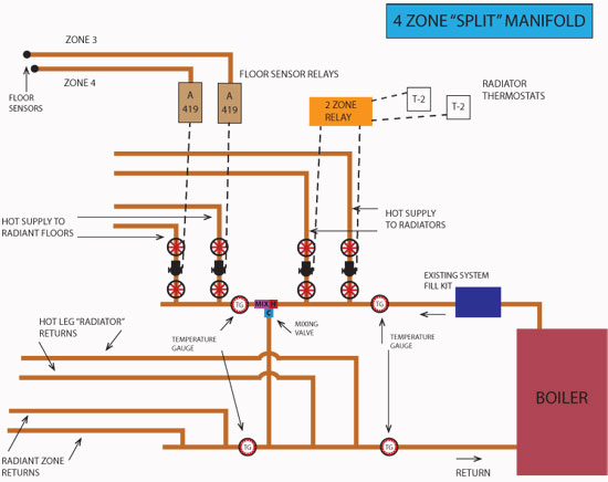
Manifold a supplies heat to the 2nd floor ceiling radiant zones each one of these zones is controlled by a separate zone valvethermostat max temp. Infloor heating system oor heating systems er the customer and dealer various options when selecting a radiant heating system. Is estimated to be 110 degrees supply.
The chief function of a control system is to modulate and limit water temperatures to maximize efficiency and to insure against over heated floors. A mixing valve is pre installed in this type of manifold. Used for hydronic heating systems such as radiant floor heating and domestic hot water.
The schematic below illustrates this approach.
Using Water Heaters For Radiant Heat
 The Closed System Diy Radiant Floor Heating Radiant Floor Company
 Radiant Heat Plumbing Diagram This Schematic For A Combi System An
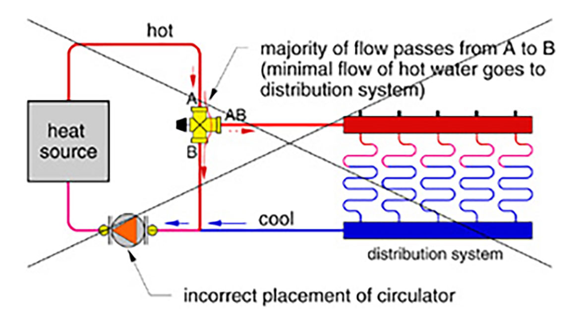
 The Do S And Don Ts Of Three Way Thermostatic Valvesjohn
 Hydronic In Floor Heat Plumbing Diagram Licensed Hvac And Plumbing
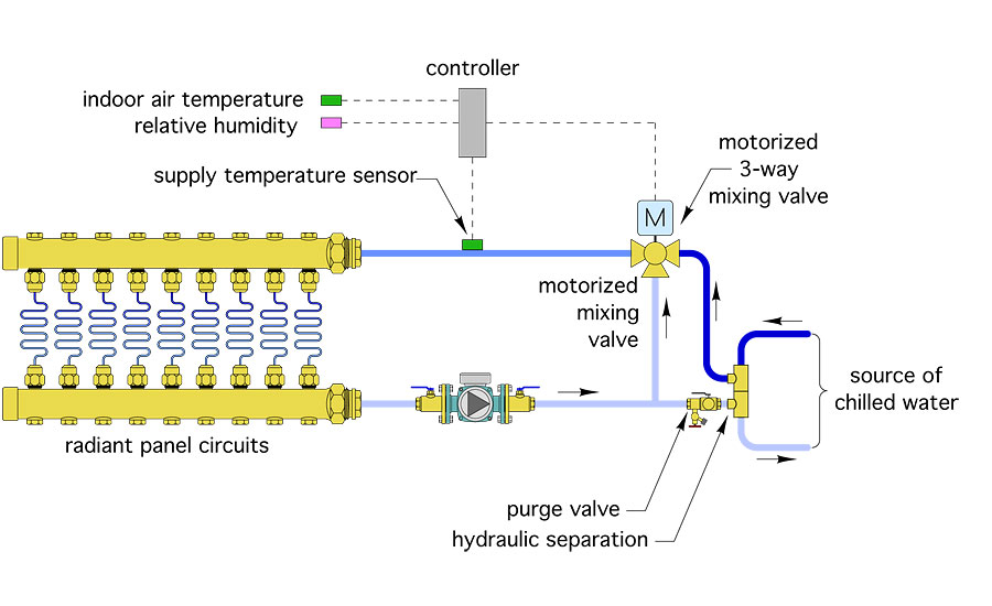 Looking Up To Radiant Cooling 2017 06 21 Pm Engineer
Adding Radiant Heat To Existing Hydronic Baseboard Heating Terry
 The Closed System Diy Radiant Floor Heating Radiant Floor Company
 The Do S And Don Ts Of Three Way Thermostatic Valvesjohn
 Taco Mixing Valve 5002 C3 G Thermostatic Mixing Valve Guage 1 2 Inch
 Radiant Mixing Valve Piping Diagram Electrical Wiring Diagram Software
 The Closed System Diy Radiant Floor Heating Radiant Floor Company


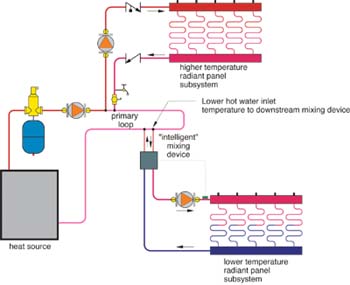 Creating Multiple Water Temperatures In Hydronic Heating Systems

 The Closed System Diy Radiant Floor Heating Radiant Floor Company
 Thermostatic Mixing Valves Applications In Plumbing And Hydronic

Using A Water Heater For Radiant Heat Hearth Com Forums Home

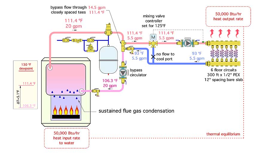 Myths And Methods For Protecting Boilers Against Flue Gas
 Confused Single Zone Systems
 Thermostatic Mixing Valves Applications In Plumbing And Hydronic

0 Response to "Radiant Heat Mixing Valve Diagram"
Post a Comment